
| Photo of the month – April 2008 Version 1.0.0.08 |
[German version] |
Low flying steel coils
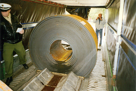
Figure 1 [U.-P. Schieder]
Figure 1 shows a hot-rolled steel coil in a special coil transporter with a coil well. No load-securing measures have been taken.
Even though the past decade has seen considerable improvements with respect to load securing, particularly with steel goods, and vehicles have been generously equipped with load-securing materials and both drivers and loading staff have increasingly been trained, loads are frequently encountered on our roads that are not secured at all or are secured inadequately.
This coil would weigh somewhere between 20 and 24 tonnes and is not secured at all. The following appropriate load-securing measures could be taken:
- Ensure that the coil well is lined with heavy-duty friction-enhancing mats.
- It is useful to load a coil such as this hard up against two central stanchions with a high load-bearing capacity. If there is any play in the sockets for the stanchions allowing them to move, this space should be filled with wood, for instance.
- The coil should be secured with at least 2 tie-down lashings to prevent it from rolling out of the coil well due to dynamic forces.
- Loop lashings using chains or belts (5,000 daN) should be employed to secure the coil against forward movement.. These loop lashings should incorporate the stanchions. When dealing with load weights such as these, it makes sense if the vehicle is fitted with load securing points with a lashing capacity of 5,000 daN. This allows each chain loop lashing to generate a securing force against forward movement of 10,000 daN (provided that two different load securing points are used and favorable angles are maintained).
- Loop lashings can also be used to secure the coil against backward movement. Often, special T-bar securing devices are used. These are lateral beams placed behind the coil at the same height as the eye. These T-bars are fitted with a load-securing point in the middle, allowing a chain (or a belt) to be attached. This is in turn passed through the eye of the coil, attached to a load-securing point and tensioned lightly. At the point of contact with the coil, these T-bars should be padded with FE mats to protect the load (at least with cold-rolled coils).
The particular risks associated with such a coil result from
| its high weight, | |
| the fact that the load is round in shape, | |
| and its very sharp edges. |
The high weight demands considerable efforts to be made in load securing. Extremely high levels of kinetic energy are generated if the load moves. The fact that the load is round in shape means that it runs the risk of rolling. It is crucial to prevent the load from rolling as rolling friction is a mere one fiftieth of normal friction.
Rolling is effectively an unhindered movement, which would have catastrophic results for such high weights. This is why such coils are also transported in coil wells.
The tilting edge of the coil depends on the point of contact between the coil and the coil well. For details, see Figure 2 and the associated table. The precise location of the points of contact of the coils depends on the size of the coil and the angles of the coil well.
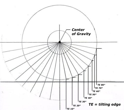
| Angle (a) | 10° | 20° | 30° | 40° | 50° | 60° | 70° | 80° | 90° |
| sin a | 0.17 | 0.34 | 0.50 | 0.64 | 0.77 | 0.87 | 0.94 | 0.98 | 1.00 |
Figure 2 and the associated table
Back to beginning