
| Photo of the month – February 2008 Version 1.0.0.08 |
[German version] |
"L on wheels"
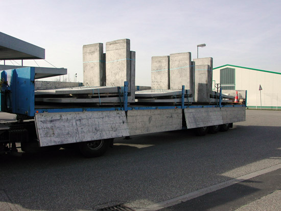
Figure 1 [R. Kessler-Kangler]
This articulated truck was loaded with 12 concrete L sections that were "secured" in almost exemplary fashion. Exemplary, because this load allows us to identify and describe shortcomings in loading and securing in a way that would hardly be possible with other loads. In describing this case, we have assumed that the L sections weigh around 2 tonnes each, which in turn means that each load unit weighs 4 tonnes. Two load units have been grouped to form a securing unit, giving a grand total of 8 tonnes per securing unit. The way in which the belts have been attached suggests that the vehicle has no load-securing points on the loading area, which makes it less than ideal for transport tasks such as this one.
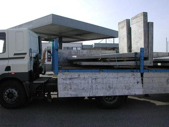
Figure 2 [R. Kessler-Kangler]
Gaps were left between the components of the load and between the load and the headboard. This was presumably done to protect the load itself and the headboard.
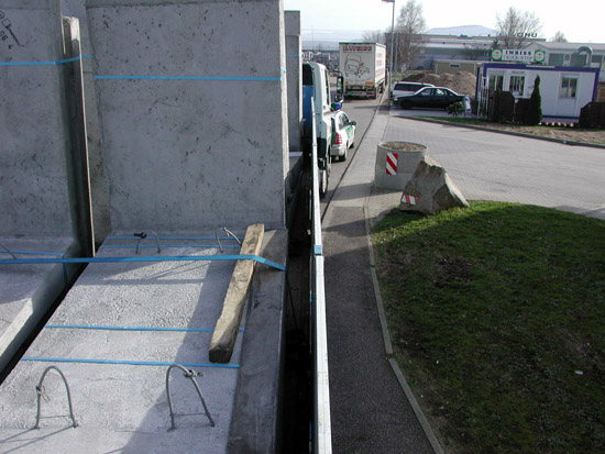
Figure 3 [R. Kessler-Kangler]
Each pair of 4-tonne load units (totaling 8 tonnes) were at least secured by one tie-down lashing. The lashing belt itself was not protected from the sharp, abrasive concrete edges. The vain attempt to protect the belt with a length of squared lumber was, of course, doomed to failure because the diagonal forces pushed the squared lumber inwards during the journey until it was stopped by the lifting eye.
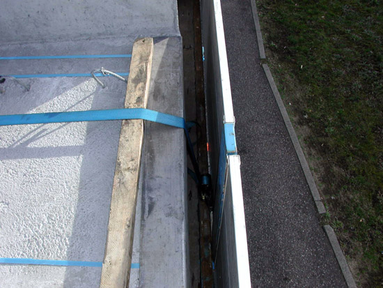
Figure 4 [R. Kessler-Kangler]
This picture clearly shows that the loading area did not provide any adequate load securing points and that the belts therefore had to be threaded under the side walls. When you consider that it has been mandatory for new vehicles to be fitted with load securing points for more than 12 years, the driver will undoubtedly have been annoyed at being forced to do all this fiddly work.
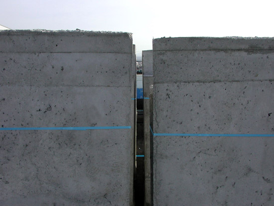
Figure 5 [R. Kessler-Kangler]
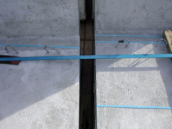
Figure 6 [R. Kessler-Kangler]
Figures 5 and 6 clearly show the gaps left between the individual load units, both along the length of the vehicle and across the loading area. This unambiguously shows that these are very significant gaps in the load. These gaps effectively reduce the effect of the tie-down lashing to zero. Lashings generate a diagonal, inward force. Vibrations and oscillations during the journey reduce the friction, with the result that the load will move inwards even over the first few kilometers of the journey. This reduces the peripheral dimensions of the load relative to the belt. The belt becomes longer relative to the peripheral dimensions of the load and the pre-tensioning is lost.
Remember: Gaps in the load make tie-down lashings worthless!
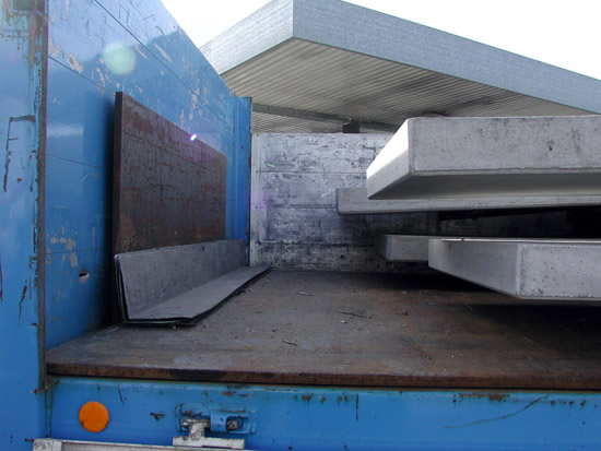
Figure 7 [R. Kessler-Kangler]
Figure 7 shows the gap between the load and the headboard and the dirty loading area. The head board appears to have been reinforced with a steel plate. This columnist is unaware of the extent to which this plate is actually suitable for load securing. The dirty loading area means that the coefficient of friction of the loading frames, which were probably made of wood, cannot be calculated, as such contamination can considerably reduce frictional forces.
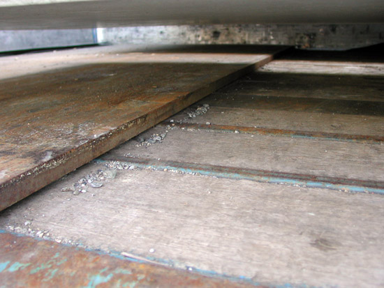
Figure 8 [R. Kessler-Kangler]
Figure 8 shows a close-up of the dirty loading area and also indicates that a simple broom can be one of the most effective "load securing measures" preparatory to loading.
Remember: Sweep first, then load!
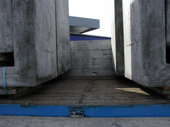
Figure 9 [R. Kessler-Kangler]
Figure 9 shows the large gaps between the individual load units along the length of the vehicle and Figure 10 shows why the side walls have so often been battered. The pallet jack that has been taken along is relatively free to move and when it makes contact with the side walls, will convert its kinetic energy to deformation energy.
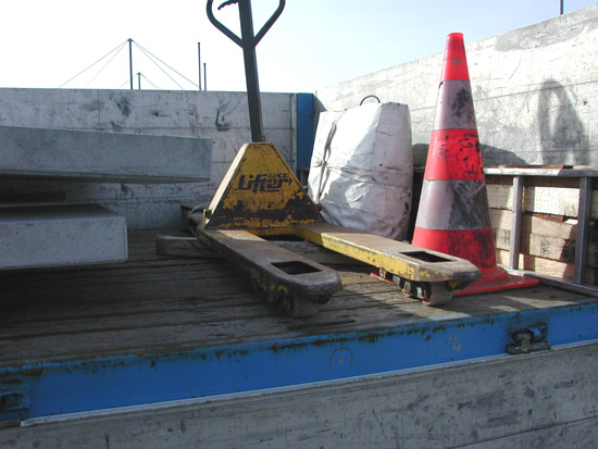
Figure 10 [R. Kessler-Kangler]
What steps can be taken to dramatically improve a load such as this?
| A suitable vehicle should/must be used. In this particular case, this columnist believes that this would involve a sufficient number of load securing points being available on the loading surface. | |
| A broom should be part of the standard equipment of the vehicle to allow the loading area to be cleaned. | |
| The use of lumber to distribute the load would allow the headboard to be used to secure at least the first two load units. | |
| The use of friction-enhancing mats would only offer limited benefits, as the individual L sections of the load units were in all probability stacked without using FE mats. | |
| The load units must be loaded as a tight fit. Squared lumber or planks can be used effectively to protect the surfaces of the concrete. | |
| Once the L sections have been loaded as a tight fit, they can be secured excellently using two loop lashings on each side. | |
| Theoretically, the L sections could be secured in the direction of travel by a single loop lashing. This would require an extremely long belt taken to the rear of the vehicle at a very shallow angle. Since securing in this way is impracticable, and the load would have too much freedom of movement as the belt stretches, we strongly recommend that two loop lashings are used. | |
| The same approach can be adopted for securing against the direction of travel. Since these belts can slip off the load, it is possible to cross the belts over the long side of the L sections (if the belts are of sufficient length). | |
| The pictures do not provide sufficient information to identify whether the L sections are liable to tip sideways despite the loop lashings. If there is even the remotest chance of tipping, this can be eliminated by bundling each pair of neighboring load units. |
Back to beginning