
| Photo of the month – July 2007 | [German version] |
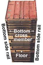
"A wolf in sheep’s clothing"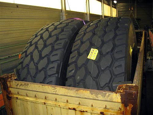 Figure 1: Rubber OTR tires in an open-top container The two huge tires (Figure 1) really don’t seem to be much of a problem. Rubber tires parked in an open-top container – what possible danger could be lurking there? But if you take a closer look, you will see that the 4-meter diameter tires are considerably higher than the open-top container and could easily present problems during transportation by road or sea. If it is transported by sea, it is not possible to stack another container on top of this one. This would make it an overheight container that would take up at least two slots on board ship. On the road, the excess height would mean that it could not be transported on a normal container chassis, but would require a lowloader. If we look at the load distribution within the container, the problem becomes more evident. The tires have a weight of 10 tonnes, which means that 10 tonnes are resting asymmetrically in the container. This asymmetric weight distribution can lead to considerable handling problems when loading and unloading a ship. This means that it is absolutely necessary to distribute the two tires over both ends of the container. 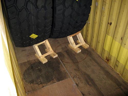 Figure 2: Well-intentioned but inadequate "loads securing measures" When you consider that each tire has a weight of 5 tonnes, the load securing measures shown in Figure 2 bear a closer resemblance to milking stools than they do to a serious attempt to secure the load. The following procedure should be adopted to secure the load intelligently and adequately: To begin with, the two tires should be offset towards the two ends of the container in order to distribute the load as far as possible. Then the line load needs to be checked. The floor of a container is made up of two longitudinal and two transverse members (see Figures 3a and 3b):
The entire load of the container is transmitted to the corner castings over these members. The longitudinal members which are located immediately below the side walls of the container are connected to transverse members which in turn support the container floor. These transverse members are significantly smaller and weaker than the main members because they only need to be able to transmit a fraction of the load of the container to the longitudinal side members. Loads must be distributed along the entire length of the container in order to ensure that sufficient transverse members bear the load. In consequence, the line load is the load that a container can accommodate over a given longitudinal distance. In the case of a normal open top container, that has a maximum payload of 28 tonnes, the line load is calculated as follows: The maximum load (28 t) divided by the length of the container (approx. 6 m) corresponds to 4.7 t in our example. This means that the floor of the container can be loaded with a maximum of 4.7 t per meter longitudinally. This rule of thumb provides a good general indication and ensures that the floor of the container is not overloaded. Some containers are capable of handling higher line loads. In this case, the manufacturer or owner must be consulted in order to establish the line load. In our example, the line load that we have determined means that the weight of each tire must be distributed over a longitudinal distance of at least 1.07 m of the container floor (1 m ÷ 4.7 t × 5 t ). This is done by laying two pieces of squared lumber measuring 10 × 10 × 107 cm on the floor and then placing the tires on them (Figures 4a and b): 
b: Top and bottom cross piece to secure the doors c: Vertical squared lumber d: Cross piece to secure the vertical squared lumber Red and blue: Lashings Figure 4a: Top view of the packed open top The same packing method shown from the side 
Figure 4b: Side view of the packed open top container We shall now check the necessary load-securing measures for transportation by road or sea and implement them theoretically or on the basis of drawings. Since the two tires have been loaded symmetrically, one at each end wall, it is possible to secure the load using a tight fit. For transport by road, 80 % of the net weight must be secured toward the ends (i.e. longitudinally). No wedges were used in this load-securing example, as they would need to be adapted for these huge tire sizes, which would be a waste of effort. Furthermore, friction cannot be taken into account because the tires are able to roll longitudinally. Therefore, the end walls must each secure the full 80 %, i.e. 0.8 × the weight of the tire. For the end walls, this means that they each have to provide 4.000 daN of securing force (0.8 × 5 t = 4.000 daN). Container end walls are always capable of securing 40 % of the payload of the container, i.e. 28 t × 0.4 = 11.2 t in our example. This means that they are theoretically capable of providing the securing force for one of the tires loaded here without any difficulty. However, since the tires apply a point load to the end wall, it is necessary to take measures to distribute the load (see Figures 4 and 5). On the actual end wall of the container (the end without the door), the load can be distributed using two pieces of vertical squared lumber secured using two cross pieces. At the door end, two pieces of squared lumber were placed vertically and the load on these was transferred to the corner posts over two pieces of squared lumber attached laterally. Under certain circumstances it is also possible to apply the load directly to the top rail of the door. To additionally secure the load, loop lashings were selected using belt material with an MSL (maximum securing load) of at least 2,000 daN (red loop lashings in figures 4a and b). This can only be done if the load securing points in the open top container can cope with an MSL of 2,000 daN. In this case, a single loop lashing per tire is adequate (shown by the red lashings in Figures 4a and b), since two load securing points at 2,000 daN each provide a total securing force of 4,000 daN. This means that the tires are secured sufficiently in a longitudinal direction with the necessary 4,000 daN securing force that we determined earlier. Note on preventing damage: The loss of strength arising from the lashing angles involved is not taken into account in this calculation. A further load securing measure to prevent the tires from tipping sideways and which should preferably be implemented using airbags increases the frictional forces (tire / container wall and tire / airbag) that compensate for the loss of securing force resulting from the lashing angle. If, as is sadly often the case, the load securing points in the container only offer an MSL of 1,000 daN, an additional loop lashing must be used on each tire as shown by the blue lashings in Figures 3a and 3b. In this case, the load is secured longitudinally using 4 load securing points providing 1,000 daN each (= 4,000 daN). Alternatively, it is possible to fill the gaps between the load and the end walls with wooden bracing (see Figures 5a and b). This is achieved using four pieces of vertical squared lumber and four wooden supports per tire. Wooden connecting pieces or diagonal bracing pieces must also be used to stabilize the construction. Even if this is done, the gap between the tires should also be filled with lumber or two airbags. 
b: Top and bottom cross piece to secure the doors c: Wooden bracing made from cross pieces (light and dark brown) and vertical squared lumber (black) Figure 5a: Top view of the packed open top The same packing method shown from the side 
Figure 5b: Side view of the packed open top It would also have been possible to distribute the load evenly in the container by loading the tires centrally. Loading the tires in this way would have concentrated the entire weight of 10 tonnes on virtually a single point in the middle of the container. Distributing such a relatively high load would have been extremely complex (see the Coils in Containers section of the Container Handbook by Professor Kaps) and not cost effective. This method of loading was therefore not discussed. |
Back to beginning