
| Photo of the month – May 2007 | [German version] |
"The enemy inside"
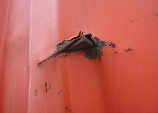
Figure 1
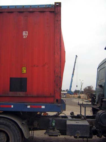
Figure 2
Whenever containers are buckled from the inside to the outside, the fault lies within the container. The dynamic loads of the journey, which will generally use different modes of transport (rail, road, sea) can cause the load to move inside the container. If load securing measures are not taken to prevent the load from moving in this way, and if there are gaps between the load and the side walls or end walls of the container, the load acts as a battering ram once it has started moving and can permanently damage the walls of the container. If in addition the components of the load are shaped in such a way that small, stable surfaces make contact with the walls of the container, it is entirely possible that they can penetrate the walls.
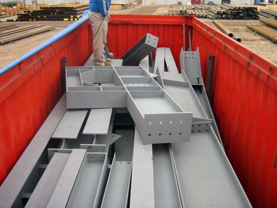
Figure 3
In this case, a load of steel construction parts was "stuffed" in a container. As is clear from Figure 3, no materials such as wood were used between the individual components of the load either horizontally or vertically to close up the gaps in the load, to increase friction and to protect the load itself from becoming damaged.
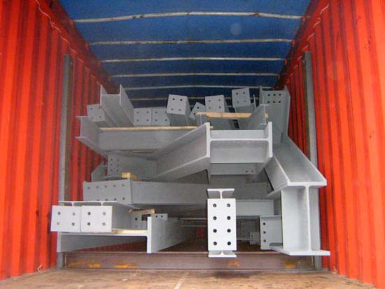
Figure 4
Figure 4 shows that at least one consideration that was in principle positive had been made. In order to facilitate unloading for the recipient, and presumably also to distribute the load in the container, cross-members were placed in the container and the steel construction parts were laid on these. But this attempt to distribute the load in the container achieved precisely the opposite effect. Like any other standard container, an open top container, is made up of bottom side rails under the side walls and a number of bottom cross-members to distribute the load of the cargo inside the container over the side rails (see section 3.1 of the Container Handbook). The cross-members placed in the container and on which the load rested would have made it easier for the recipient to unload the cargo by crane, but the entire load of the construction parts is concentrated on only two bottom cross-members of the container. Instead of distributing the load in the container across several bottom cross-members, for instance by additional members laid longitudinally, this approach concentrates the load on two points, which causes local overloading in the container and can damage the floor assembly.
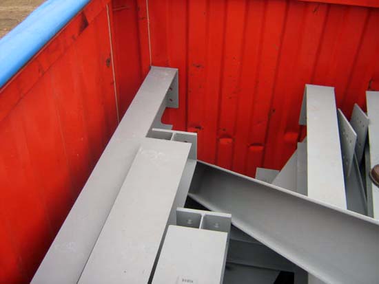
Figure 5
Direct lashings should always be used to secure loads in a container which is to be transported by sea for at least part of the journey. On the one hand, the load can be secured by shoring it with lumber. This involves bracing any remaining gaps with lumber and applying a slight degree of pre-tensioning so that the load has no opportunity to move or tip in any direction. Additionally, direct lashings provide a good securing option. Direct lashings can be made of a very wide variety of load securing materials and are generally achieved by means of loop lashings or bundling.
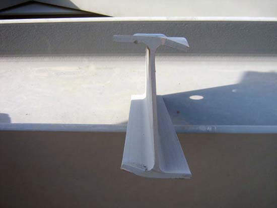
Figure 6
Figure 6 clearly shows that even the steel parts have been badly damaged as a result of movement in the container. To prevent the individual components of the load from damaging each other, each layer should be separated by intermediate layers of lumber, either boards or squared lumber. If the load is susceptible to damage, the individual steel parts must also be separated from each other by lumber inserted vertically. This results in a kind of vertical and horizontal sandwich construction forming a firm cargo block with no gaps that can be loaded. If it is not possible to load the cargo as a single cargo block, it is necessary to load a number of different cargo blocks, each of which must be secured separately.
Securing steel parts in an open top container is problematic, because the load securing points in a standard container only provide a lashing capacity (LC) of 1,000 daN. Some load securing problems cannot even be solved with a lashing capacity of 2,000 daN. In such cases, tight-fit securing using lumber shoring or the use of a flatrack container are suitable options. On the one hand, a flatrack provides stronger, easily accessible load securing points on the longitudinal support members and, on the other, unlike in a standard container, the use of the cross-members shown in Figure 4 allows the loads to be distributed excellently across the longitudinal support members of a flatrack. If the load must be protected from the environment, the only option is to use strong tarpaulins or open top containers.
Lumber shoring is ideal to close up the large loading gaps at the end walls. In order to minimize the effort involved, it is worth considering whether the individual beams that have been placed on top of the entire cargo block could not be stowed in the gaps below the first layer. More compact loading in this manner means that the effort involved in securing the load can be significantly reduced. You can find examples of how to secure loads like this in the Container Handbook in section 5.2.1.3 – Heavy plant parts and section 5.2.1.4 – Pipe frame on 20′ flatrack.
Back to beginning