
| Photo of the month – December 2005 | [German version] |
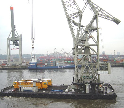
Figure 1 [Jörg Fabel, Alberts & Fabel, Seevetal]
Railroad track building locomotives safely on their way!
The picture shows two special locomotives en route to South Korea. They are railroad track building locomotives used for compressing the track ballast and are to be shipped overseas in a container ship via Hamburg. Each locomotive weighs in at 59.7 tonnes.
The locomotives are delivered alongside the container ship and loaded with a floating crane.
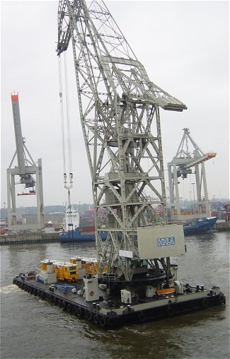
Figure 2 [Jörg Fabel, Alberts & Fabel, Seevetal]
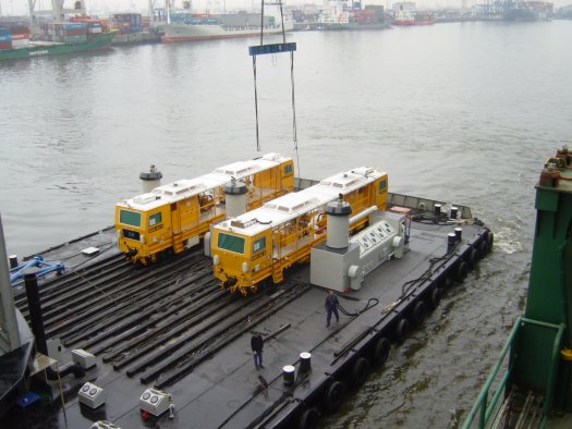
Figure 3 [Jörg Fabel, Alberts & Fabel, Seevetal]
On the container ship, the locomotives will be stowed below deck. An area midships with sufficient overhead clearance has been selected. Eight 40′ flatracks have been stowed next to each other in the penultimate tier. The locomotives will then be stowed athwartships on these flats. The collapsible end walls of the flats have been raised in order to reduce any possible torsional movement from the cell guiderails of the container ship.
To distribute the weight of the cargo evenly across the flats, two cross-laid frames comprising pairs of 18 x 18 cm squared lumber have been prepared for each locomotive. The load is distributed to the frames of the flats (side rails). Line loads are used for calculation purposes for flats and containers, in particular with static loads. Bending moments would also need to be taken into account if the cargo and the flats were to be transshipped together.
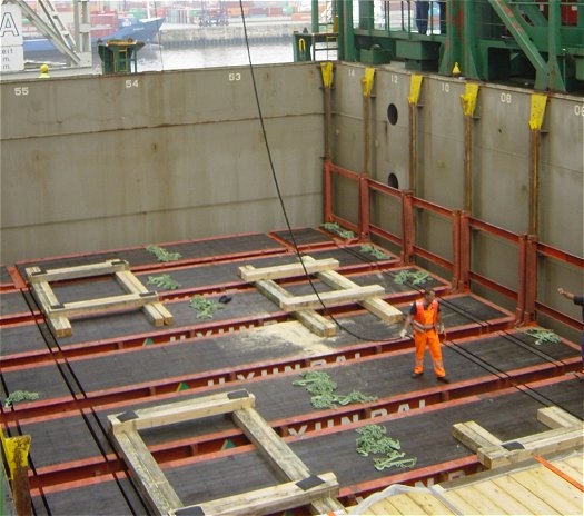
Figure 4 [Jörg Fabel, Alberts & Fabel, Seevetal]
A cross beam is used during transshipment to ensure that the wire ropes used for slinging can run vertically. If there is a spreading angle, there is a risk that the roof of the locomotive could be damaged by lateral pressure from the slinging equipment.
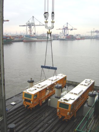
Figure 5 [Jörg Fabel, Alberts & Fabel, Seevetal]
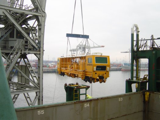
Figure 6 [Jörg Fabel, Alberts & Fabel, Seevetal]
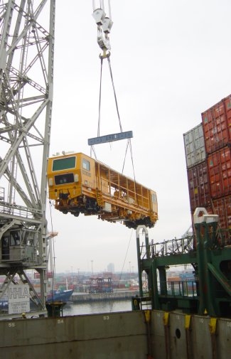
Figure 7 [Jörg Fabel, Alberts & Fabel, Seevetal]
The cargo is slowly lowered onto the frames in the container hold. The frames are aligned so that the bogies of the locomotive can be lowered onto them exactly.
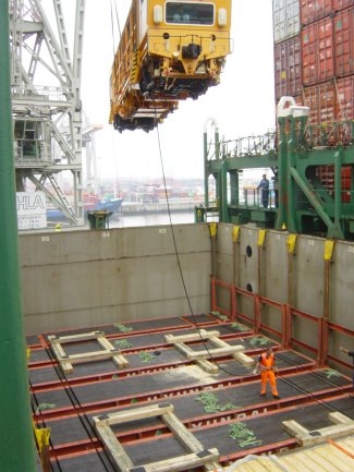
Figure 8 [Jörg Fabel, Alberts & Fabel, Seevetal]
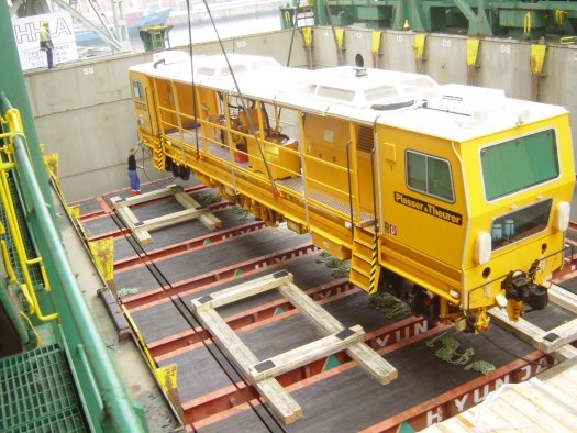
Figure 9 [Jörg Fabel, Alberts & Fabel, Seevetal]
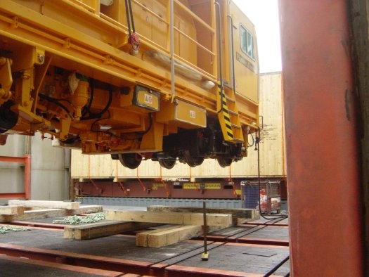
Figure 10 [Jörg Fabel, Alberts & Fabel, Seevetal]
Before the locomotive is finally completely lowered, specially built hardwood cradles are placed below the wheels.
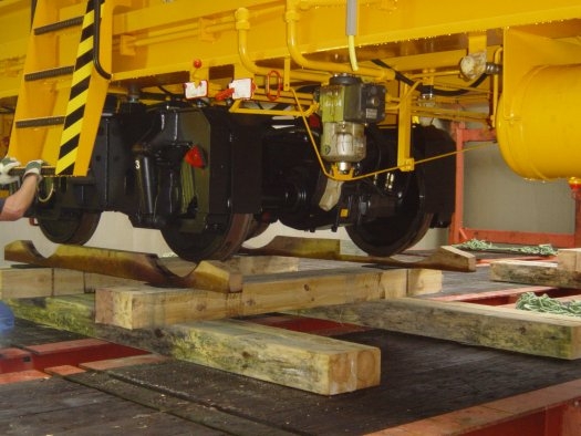
Figure 11 [Jörg Fabel, Alberts & Fabel, Seevetal]
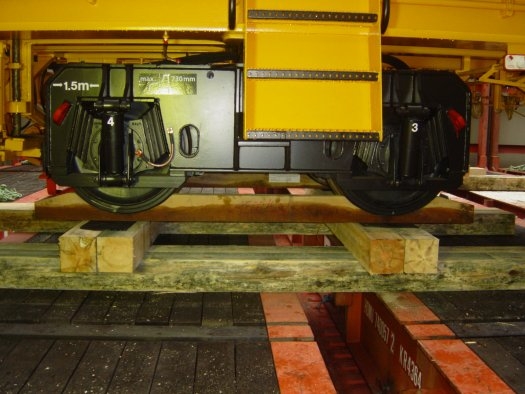
Figure 12 [Jörg Fabel, Alberts & Fabel, Seevetal]
The second locomotive is then loaded using the same method.
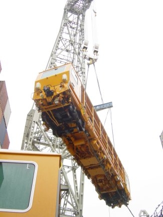
Figure 13 [Jörg Fabel, Alberts & Fabel, Seevetal]
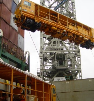
Figure 14 [Jörg Fabel, Alberts & Fabel, Seevetal]
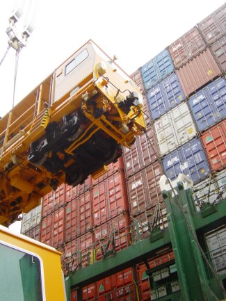
Figure 15 [Jörg Fabel, Alberts & Fabel, Seevetal]
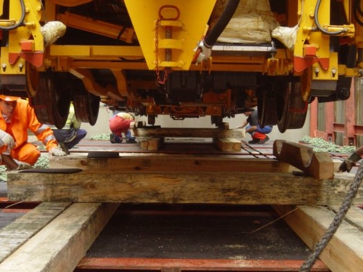
Figure 16 [Jörg Fabel, Alberts & Fabel, Seevetal]
Each of the locomotives is then secured directly against tipping longitudinally and against slipping longitudinally and laterally with 24 lashing chains. Figure 17 indicates the arrangement of the lashing chains.
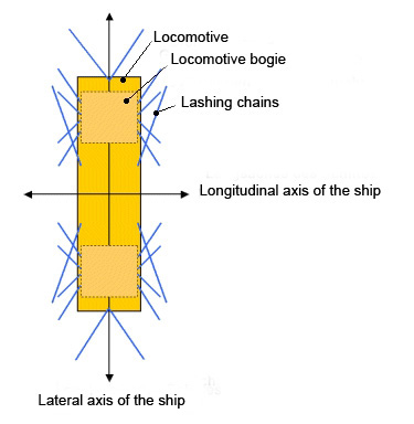
Figure 17
The chains used have a certified breaking load of 200 kN (20 tonnes), i.e. an MSL (maximum securing load) of 100 kN (10 tonnes) and are tensioned using tensioning levers and hooks. The load securing points of the flats have an MSL of 5000 daN (5 tonnes). The smaller value must be taken for calculating the load securing measures. Experience shows that not all the lashing points are always accessible, and so sturdy points on the frames of the flats can be used instead. The studs of the stanchions are not suitable as securing points and can only be used as additional securing.
With any vehicles, care must be taken to ensure that the load securing measures do not push the vehicle down on the suspension. In the case described here, the majority of the lashing chains were attached to unsprung parts – the bogies. The remaining chains were attached in long runs to avoid pulling the vehicle down on its suspension and to ensure that the effect was exerted in a lateral direction.
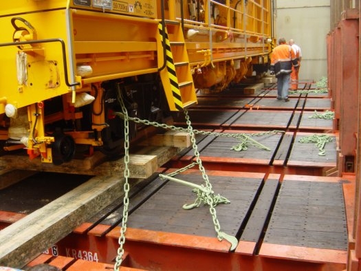
Figure 18 [Jörg Fabel, Alberts & Fabel, Seevetal]
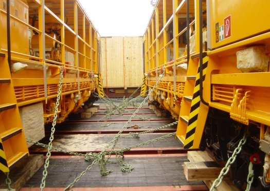
Figure 19 [Jörg Fabel, Alberts & Fabel, Seevetal]
When transporting heavy cargo or non-standardized cargo on ocean-going ships, Annex 13 of the Code of Safe Practice for Cargo Stowage and Securing (IMO-Code) is to be observed.
The following aspects should be observed with direct securing using chains:
| The maximum securing load (MSL) of lashing chains and lashing points is 50 % of their rated breaking load. | |
| To account for an uneven distribution of the effective securing forces, (e.g. incorrect deployment of the load securing equipment), the MSL is reduced by a factor of 1.5 when calculating the necessary load securing measures. This means that the calculation strength (CS) is calculated as follows: CS=MSL/1.5. | |
| The lashing equipment should be attached symmetrically where possible and should be evenly pre-tensioned. Pre-tensioning should be kept very low with direct securing, but the securing equipment should nevertheless show no slack. | |
| The securing equipment should be attached flush with the cargo to be secured to achieve the highest possible horizontal securing forces. | |
| At least four lashing chains should be used to avoid movement and rotation. | |
| Anti-friction material should be used to increase friction. |
The following points should also be observed:
| Lashing chains should not be twisted and should be free of tension when they are attached. This prevents vibrations or other influences from introducing slack into the chains subsequently. | |
| In addition to a symmetrical arrangement, the homogeneity of the load securing measures is also important; this ensures that the securing equipment used is loaded simultaneously, and not at different times. | |
| When transporting heavy cargo on container ships, the maximum stack weight of a slot must be observed. | |
| Incorporating elements of the ship’s structure (e.g. cell guiderails) into the lead securing measures is to be avoided, since the torsional forces of the ship and the cargo-bearing surface may be different, which can lead to uneven loading of the load securing equipment. | |
| Securing equipment should only be attached to the flats which actually bear the weight of the cargo. |
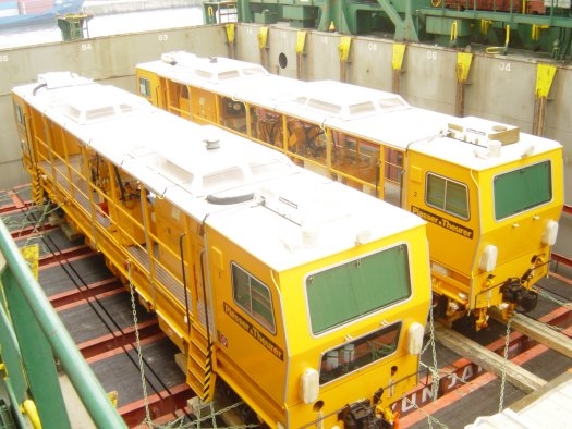
Figure 20 [Jörg Fabel, Alberts & Fabel, Seevetal]
After the securing work is completed, the container hold is covered with pontoon covers and several layers of containers stowed on top.
Back to beginning