
| Photo of the month – March 2005 | [German version] |
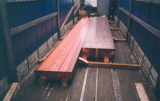
Figure 1: View towards the rear of the vehicle
Two "heavies" pulled out of circulation just in time!
The figures show a semitrailer (a curtainsider) loaded with semi-finished copper cakes. The police came across the vehicle during a truck inspection.
Load securing of the two cakes totaling some 24 tonnes can only be described as extremely deficient. We don’t have any detailed information available, but the pictures alone allow some clear conclusions to be drawn with respect to the suitability of the vehicle and the load securing measures.
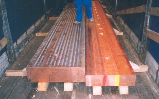
Figure 2: View towards the front end wall
It can be seen that the cakes are loaded on dunnage. The cake on the left in the direction of travel weighs around 13 tonnes, and the one on the right around 11 tonnes. Wedges were used to brace or "secure" the load.
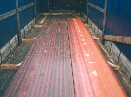
Figure 3: View towards the front end wall
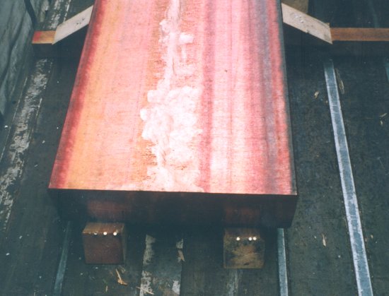
Figure 4: Wedges mounted incorrectly
Longitudinally, i.e. to the front and rear, two wedges were fitted per cake. These were attached to the floor (30 mm thick) with three nails each. The wedges are mounted incorrectly. In addition, the nails have been driven into the point of the wedge, so that the nails do not penetrate the vehicle floor sufficiently, which is too thin anyway. The securing effect can be assumed to be extremely small (cf. Figure 5).
At each side, four wedges are mounted with three nails each. There is a gap between some of these wedges and the load. The nails have been driven in along the grain, with the result that the wood has split to some extent. The wedges are attached to the dunnage, and it is unlikely that these nails penetrate the vehicle floor (cf. Figure 6). Furthermore, the dunnage itself is not attached to the vehicle floor. Thus, it is only the friction between the wooden dunnage and the vehicle floor that provides any lateral load securing. This means that the two cakes are resting on wooden runners, just waiting for the next significant lateral acceleration force to slip from the loading area. The following calculations will show that the load is just as liable to slip forwards as a result of the deficient load securing.
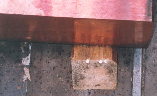
Figure 5: Wedge mounted incorrectly
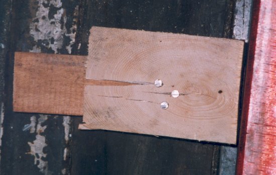
Figure 6: Wedge mounted incorrectly
Analysis of the securing in place:
As a general principle, it should be noted that this semitrailer is utterly unsuitable for tight-fit securing using bracing.
| No edges to the loading area or edges which will not withstand a high enough load (no side walls, light end wall) mean that it is not possible to secure the cakes by means of a tight fit using bracing. | |
| The structure of the vehicle floor (wood/metal frame) and the material of the floor (30 mm wood) are not suitable for securing by nailed wooden wedges. | |
| The different dimensions and weights cause problems when stowing the cakes next to each other (distribution of the load). In this case, the vehicle is loaded more to the right (viewed in the direction of travel). |
| Securing action of the nailed wedge securing in a longitudinal direction (to the front, to the back): | Securing action of the nailed wedge securing in a lateral direction: | |||
| Not only is the vehicle a poor choice, but serious errors were also made in using the wedges. The calculation below for securing towards the front of the vehicle shows that only 44% of the necessary securing force has been achieved: | The calculation below for securing towards the side of the vehicle shows that only 60% of the necessary securing force has been achieved: | |||
| The inertia force to be secured in the longitudinal direction is 0.8 g* of the load weight (i.e. 80% of the weight of the load). The required securing force to the front for each cake is thus: a) 11,000 kg x 0.8 g = 8,800 daN b) 13,000 kg x 0.8 g = 10,400 daN * [g = 9.81 m/s2–> 10.0 m/s2] |
The inertia force to be secured in the lateral direction is 0.5 g* of the load weight (i.e. 50% of the weight of the load). The required securing force to the side is thus: 24,000 kg x 0.5 g = 12,000 daN * [g = 9.81 m/s2–> 10.0 m/s2] |
|||
| Securing force created by friction, assuming a frictional coefficient of µ = 0.3 between the wood and the copper cake: a) 11,000 kg x 0.3 g = 3,300 daN b) 13,000 kg x 0.3 g = 3,900 daN |
Securing force created by friction, assuming a frictional coefficient of µ = 0.3 between the wood and the wood/metal combination: a) 24,000 kg x 0.3 g = 7,200 daN |
|||
| At this point, the securing force still required is: a) 5,500 daN b) 6,500 daN |
At this point, the securing force still required is: 4,800 daN |
|||
| Securing action of the wedges: Even though the wedges were mounted incorrectly, a securing force of 100 daN per nail was assumed. This results in a securing force of 300 daN per wedge, i.e. 600 daN for each cake. | Securing action of the wedges: As already mentioned, the dunnage is not attached to the vehicle floor, which means that the wedges exert no securing force. | |||
| Shortfall in securing force: a) 5,500 daN – 600 daN = 4,900 daN b) 6,500 daN – 600 daN = 5,900 daN |
Shortfall in securing force: 4,800 daN |
|||
| In total, there is a shortfall of 10,800 daN of the required 19,200 daN securing force to the front. | Laterally, only 7,200 daN of the required 12,000 daN securing force to the side is achieved. |
|||
Securing to the rear: The inertia force to be secured to the rear is 0.5 g* of the load weight (i.e. 50% of the weight of the load). Without working through the complete calculation, this results in: |
Assuming that the dunnage was properly attached to the vehicle floor and that the securing action of each of the four wedges (with three nails each) was 300 daN despite their deficiencies, there is still a shortfall of 3,600 daN. | |||
| Shortfall in securing force: a) 1,600 daN b) 2,300 daN In total, there is a shortfall of 3,900 daN of the required 12,000 daN securing force to the rear. |
||||
The following information should indicate how wooden wedges are used correctly
Crate wedges should be attached as shown in figure 7. For each wedge, at least three nails are necessary, one tension nail and two to hold the wedge in place. The tension nails have the task of pulling the wedges tight into the load. The holding nails take up the load and are driven in vertically or at a slight angle to the direction of loading. Shear strength and extraction resistance are influenced by the penetration into the underlying surface, the angle at which the nail is driven in, and the properties of the nail surface. The shear strength and extraction resistance of a nail, 5 mm thick, that is driven in vertically and which penetrates through 50 mm of the grain side of a piece of wood, and is driven in to a depth of 40 mm can be expected to be around 400 daN. The critical factor is that the grain side of the wood is used to take the nails (cf. Figures 8 and 9). Nailing into the grain can cause the wood to split during nailing and experience shows that this only results in around half the extraction resistance of a nail driven into the grain side.
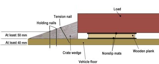
Figure 7
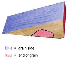 Figure 8: A wedge (crate wedge) that has been sawn correctly allows nails to be driven into the grain side of the wood. |
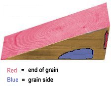 Figure 9: This cannot be used as a crate wedge, as it would be necessary to drive the nail into the grain. If it were placed on the red surface, this wedge could be used as a pipe wedge. The nail could be driven into the grain side and the side against which the load rests is chamfered to take cylindrical goods. |
With heavy loads, nailed load securing methods should not be the only means of securing used; too many factors impact precise calculation of the holding force of a nail:
| Nature of the floor of the means of transport (e.g. strength of the wood, thickness of the wood, moisture content of the wood) | |
| Nature of the chock (e.g. strength, thickness, moisture content, splitting) | |
| Nature of the nail (e.g. diameter, coating) | |
| Penetration depth through chock and penetration into floor of the means of transport |
Conclusion: For this type of load, vehicles with stanchions, strengthened headboard and/or adequately dimensioned lashing points should be used. In this way, the load can be secured efficiently and quickly with the aid of nonslip material and by filling gaps with wood or by using loop lashings.
Illustration of effective securing methods
Vehicles with adequately dimensioned lashing points and/or standardized end and side walls permit the use of a number of different load securing techniques which are simple to implement. The following illustrations are only intended to give an insight into the load securing methods which can be considered. We shall not discuss whether the load should be stacked or stowed side by side.
Care should be taken to ensure that the dunnage is wider than it is high. Dunnage that is higher than it is wide encourages a tendency to tip and square dunnage tends to roll. In addition, dunnage should be combined with nonslip materials (cf. Figure 10).
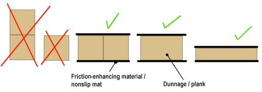
Figure 10: Use of dunnage combined with nonslip material
When nonslip material is used with heavy loads, physical changes may occur in the material which have a negative impact on their coefficient of friction. For this reason, a coefficient of friction of µ=0.5 is assumed below where nonslip mats are used.
Load distribution considerations forbid tight-fit loading against the headboard of the vehicle. Against this background, the following calculations were made for securing with "loop lashings (V lashings)" and "wooden bracing against the headboard".
| I. Securing in a longitudinal direction (to the front, to the back): | II. Lateral securing: | |||
| The inertia force to be secured in the longitudinal direction is 0.8 g* of the load weight (i.e. 80% of the weight of the load). The required securing force to the front is thus: a) 11,000 kg x 0.8 g = 8,800 daN b) 13,000 kg x 0.8 g = 10,400 daN * [g = 9.81 m/s2–> 10.0 m/s2] |
The inertia force to be secured in the lateral direction is 0.5 g* of the load weight (i.e. 50% of the weight of the load). The required securing force to the side is thus: 24,000 kg x 0.5 g = 12,000 daN * [g = 9.81 m/s2–> 10.0 m/s2] |
|||
| Securing force as a result of friction; µ = 0.5: a) 11,000 kg x 0.5 g = 5,500 daN b) 13,000 kg x 0.5 g = 6,500 daN |
Securing force as a result of friction; µ = 0.5: 24,000 kg x 0.5 g = 12,000 daN |
|||
| At this point, the securing force still required is: a) 3,300 daN b) 3,900 daN |
Theoretically, the friction force is sufficient to secure the load laterally. Nevertheless, additional securing measures should be put in place to increase the safety margin. | |||
Calculation of two securing methods to achieve the securing force still required: |
||||
| I. a) Longitudinal direction: Loop lashings (V lashings) with lashing belts: On the assumption that the load securing points of a vehicle have a lashing capacity (LC) of 2,000 daN and that each belt is attached to two different load securing points, two V lashings must be used on each cake to provide forward securing. One loop lashing attached to two load securing points provides a securing force of 1 x 2 x 2,000 daN = 4,000 daN. The angle of spread causes up to 10-20% of the securing force to be lost, with the result that in the worst case, 3,200 daN securing force is available per lashing (cf. Figure 11). If four lashings are used, 6,400 daN securing force is available for each cake. |
II. a) Lateral direction: Loop lashings (V lashings) with lashing belts: On the assumption that the load securing points of the vehicle have a lashing capacity (LC) of 2,000 daN and that each belt is attached to two different load securing points, two V lashings must be used on each side to provide lateral securing. Two loop lashings attached to two load securing points each provide a securing force of 2 x 2 x 2,000 daN = 8,000 daN. The angle of spread causes up to 10-20% of the securing force to be lost, with the result that an additional 6,400 daN securing force is available per lashing (cf. Figure 12). |
|||
| I. b) Longitudinal direction: Tight fit to edge of loading area (headboard) using wooden bracing: Assuming that the headboard meets the standard whereby it is capable of withstanding a load of 40 % of the permissible payload, and that the load is distributed evenly as shown in Figure 13, this results in a load capacity of 0.4 x 24,000 kg = 9,600 kg –> 9,600 daN. The total securing force of 7,200 daN which is still required is thus achieved. |
II. b) Lateral direction: Tight fit to edge of loading area (e.g. stanchions) using wooden bracing: Assuming that the side edge of the loading area comprising 6 stanchions meets the standard whereby it is capable of withstanding a load of 30 % of the permissible payload this results in a load capacity for each stanchion of 0.3 x 24,000 kg / 6 stanchions = 1,200 kg –> 1,200 daN. Figure 14 shows how the load can be braced against the stanchions. |
|||
| Figures 15 and 16 show other longitudinal securing methods. | ||||
| Securing to the rear: The inertia force to be secured to the rear is 0.5 g* of the load weight (i.e. 50% of the weight of the load). Without working through the calculation, this results in the following for both cakes together: Required securing force minus securing force from friction (µ = 0.5): 12,000 daN – 12,000 daN = 0 To the rear, the load is held by friction alone. Nevertheless, additional securing measures should be put in place to increase the safety margin (e.g. V lashings or bracing against stanchions). |
||||
Sketches for the calculations described above:
Figure 11: Sketch of longitudinal securing using loop lashings (view from above) – cf. calculation I.a). The dunnage should not extend for the full width of the cakes to allow the lashings to pass under the cakes. Edge protectors should be used with the lashings. This securing method can also be used with stacked loads. Loads stowed side by side require gaps to make it easier to subsequently unload the cargo (slinging with chains or belts). These gaps should be filled with squared lumber.
Figure 12: Sketch of lateral securing using loop lashings (view from above) – cf. calculation II.a). Edge protectors should be used with the lashings. This securing method can also be used with stacked loads. Gaps between the load items should be filled with squared lumber.
Figure 13: Sketch of longitudinal securing by means of bracing against a load-bearing headboard (side view) – cf. calculation I.b.). Bracing comprising crosspieces, supports and locking battens distribute the load evenly across the headboard. This securing method can also be used with loads stowed side by side.
Figure 14: Sketch of lateral securing by means of bracing against a load-bearing side stanchions (view from rear) – cf. calculation II.b.). This securing method can also be used with loads stowed side by side.
Figure 15: Sketch of longitudinal securing using a combination of bracing against load-bearing side stanchions and loop lashings (view from above)
Figure 16: Sketch of longitudinal securing using a head loop (side view / view from top); lashing equipment (chains/belts and load securing points) must be adequately dimensioned.
[bvd]
Back to beginning