
| Photo of the month – November 2022 |
[German version] |
Container feet!
“Small feet, narrow and tall, more often than not lead to a fall.”
Although we probably won’t get a Pulitzer prize for that ditty, it is of huge relevance to this load. A load that is liable to tip coupled with extremely high point loads.
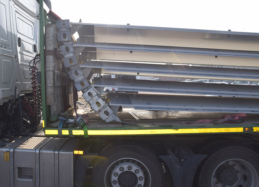
Figure 1 [Michael Zein]
So what can we see on this picture of the month? Steel elements lying lengthwise and flat, with corner fittings from containers used to allow them to be stacked, and all joined together by twistlocks.
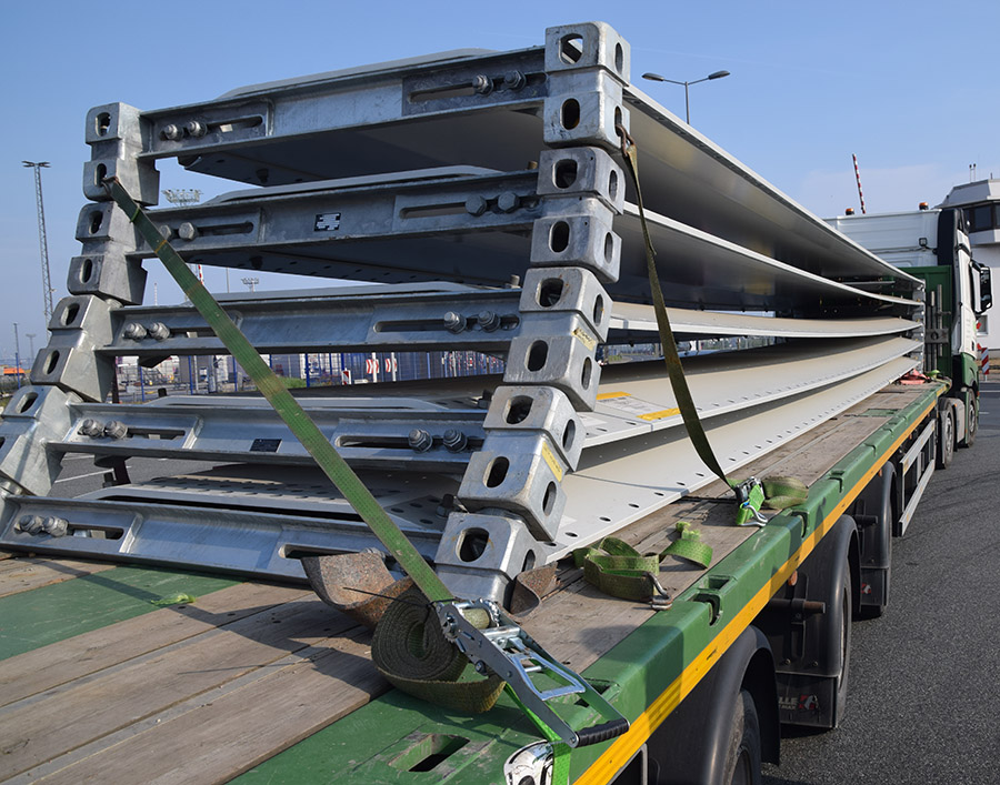
Figure 2 [Michael Zein]
The construction is smart and seems to be very stable. Two container corner fittings are always connected with a rail into which the flat steel elements can be inserted and fastened by means of a screw connector. The groove created between the corner fittings makes an ideal guide for the belts.
The load has been secured with a “diagonal lashing”. It is simply a direct lashing arranged crosswise, which makes no sense. The horizontal component of this method of securing the load against movement in the direction of travel is negligible and thus a waste of time, material and money.
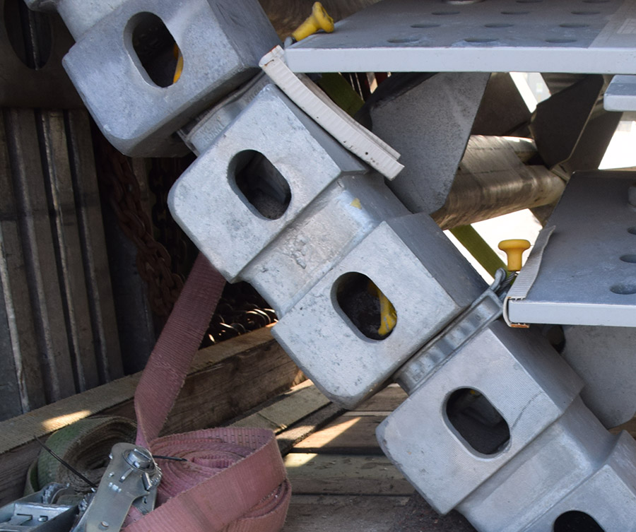
Figure 3 [Michael Zein]
The problem with this idea for holding the load is the way in which the corner fittings are connected to each other with twistlocks. These are meant for securing containers and can therefore withstand very high loads. In principle, this is a good idea and provides an extremely stable connection. But the undoing of this loading method, among other things, is the play or slack in the twistlocks, which can be seen very clearly in this photo. When stacking containers, this play does not present a problem, because the diagonal stiffness of the containers themselves means that they are well able to withstand diagonal shear forces. The cargo that was “clamped in place” here was only secured with screw connections, so it was not able to absorb diagonal shear forces to stabilize the stack. This stabilization would need to be provided by external securing measures. But it wasn’t!
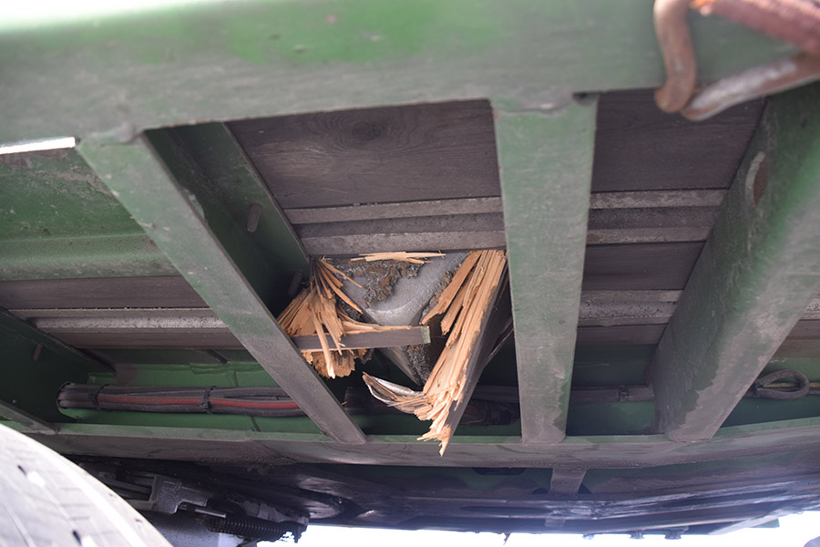
Figure 4 [Michael Zein]
The second problem with this load is the high point loads. Container corner fittings are very stable and can transmit high forces. However, containers are usually transported on beds designed for this purpose, which have specially designed mountings with twistlocks. A normal loading bed cannot absorb these forces and certainly not when the corner fittings are also tilted and the entire load is applied as a line load. The result that we see here is truly impressive!
Originally, the load was positioned exactly on the green cross member, because those responsible for loading were obviously aware of the fact that the point load was too high for the loading bed. Unfortunately, when subjected to a load (emergency braking from just 18 km/h), the cargo could slip forward and even tip over.
Good intentions do not always yield good results. Constructions and securing measures such as this must be systematically thought through.
A lot of time, effort and money was invested in this loading method, probably also because the construction can be reused several times. Unfortunately, the frames do not have the same dimensions as containers, so it is not possible to use traditional container trailers. But we can make use of the idea of using containers securing methods. We would take two steel plates that are the same width as the vehicle. Angle brackets would have to be welded to the sides to secure the load laterally. This means that the plates would be lying on the vehicle with a tight fit to the sides. The twistlocks would then be positioned and welded to the plates so that they match the dimensions of the frames. The steel plates (or frame constructions) are so wide that they do not permit tipping.
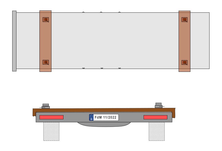
Diagram 1 [Photo of the Month]
Because the loading frames are liable to tip to the front and to the rear due to the play in the twistlocks, they need to be secured with several direct lashings. How we would do it:
- Determine the weight of the top four frames. The lowest one is secured to the plate as a tight fit using twistlocks and therefore does not need to be additionally secured against tilting.
- The basis of the calculation is a full 0.8 g to the front, because the aim is to secure the relatively free-floating tower of corner fittings in such a way that it can barely move.
- We assume 16 tonnes (4 x 4 tonnes).
- Of course, the steel plate on the loading bed is resting entirely on anti-slip material or anti-slip material is permanently glued to the steel plate. This saves fiddly work when positioning the plate on the loading bed.
- To calculate the securing force required to the front, we take the weight force of 16,000 daN and multiply it by 0.8 to find the 80 % of the force that can act to the front. This gives 12,800 daN.
- Regular readers of our column will already have guessed what is coming next: That’s right! Head loops. In plain language, this means that we make maximum use of the “intelligence” of the belts by taking them around the front of the load. They can be placed and guided in the grooves created between the corner fittings very well without the risk of slipping off.
- We shall go for very long belts to achieve the smallest possible angles.
- We shall place the tensioners on alternate sides so that the pre-tensioning force is evenly distributed right from the start.
- The number of belts is easy to calculate: 12,800 daN / 4,000 daN results in four against movement to the front.
- We can check the actual horizontal effect of the belts (resulting from the angles to the loading bed) with the “cookbook” that we have already presented in our column quite often, so we will not repeat it today.
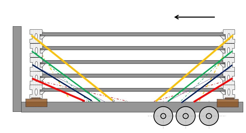
Diagram 2 [Photo of the Month] - It is important that the belts are placed alternately so that they are all of equal length as far as possible, otherwise the shortest belt will be subjected to the greatest load and the longest belt the smallest load. The two diagrams should make this clear!

Diagram 3 [Photo of the Month] - Because of the geometry of the load, the top belt is slightly longer, so we increase the pre-tensioning force slightly and place a fifth belt of the same length as the other belts over it. If this is not possible or difficult to achieve, two separate direct lashings can be attached to the rear of the load. But not crosswise!
- Since the load is only relatively loosely stacked, it must be secured to the rear in much the same way, against an acceleration of 0.5 g. In addition, the pre-tensioning force from the front must be absorbed by the load securing equipment at the rear. And the same applies the other way round.
- We do not use the maximum pre-tensioning force, but we take great care to ensure that the frames do not slip into loose belts when subjected to a load.
- The idea the pre-tensioning force for direct lashings that act against each other (to the front / rear) decreases the actual securing force is a myth, because the load must move a little in order for a direct lashing to develop its full securing force. And, of course, it does. If the vehicle brakes, the load is accelerated forward relative to the vehicle, and our tower of corner fittings tries to tilt forwards. This tensions the belts, which restrain the load. The forward movement of the load relieves the pressure on the rear belts. The pre-tensioning force on these belts decreases and is now available for securing the load from moving forward.
Your load securing columnists wish you a safe and relaxing autumn.
Back to beginning