
1 Assessment of suspension arrangements |
[German version] |
1.1 Principles of suspension stabilityIn popular language the term stability is quite often used for designating strength or sturdiness of a technical arrangement. In this paper stability stands exclusively for the quality of a suspension arrangement to remain in a desired, normally upright condition and not to overturn after lifting has commenced. Suspension arrangements are absolutely stable, if the centre of gravity of the cargo unit is situated below the level of the lifting points on that unit. Such lifting points may be trunnions, eye plates or other connections for slings or shackles. In the case of a belly sling arrange-ment, the highest points of contact of the slings to the cargo unit indicate the level of lifting points (Figure 1.1). 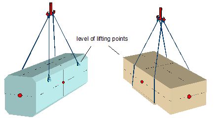 Figure 1.1: Absolutely stable primary suspensions If the centre of gravity is situated above the level of lifting points (Figure 1.2), the arrangement is potentially unstable. In any of such cases the arrangement should be checked for a positive „metacentric height“. 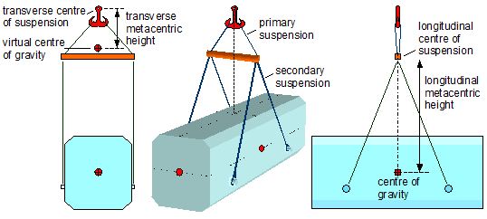 Figure 1.2: Potentially instable primary/secondary suspension arrangement Figure 1.2 shows a suspension arrangement with different metacentric heights in the transverse and longitudinal orientation. The following definitions are applicable:
Remark for nautical professionals: There is an immediate analogy between the suspension stability and the stability of a ship and her metacentric height GM. The centre of suspension corresponds to the metacentre of the ship. The virtual centre of gravity in a suspension arrangement corresponds to the virtual centre of gravity of a ship obtained by the KG-correction for liquid free surfaces in tanks, i.e. the slewing secondary suspension has an ef-fect similar to that of the travelling liquid in a partly filled tank.The determination of the virtual position of the centre of gravity requires a geometrical analy-sis of a combined primary/secondary suspension using the following parameters:
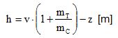
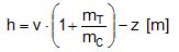
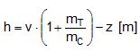
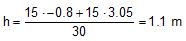
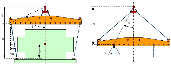 Figure 1.3: Definition of f, g, v, s and z Figure 1.3 shows the definition of the geometric parameters. The angle f is measured be-tween the vertical and the line from the centre of suspension to the pivot of the secondary suspension. The angle g is given the negative sign when the secondary slings point inward. Top of page 1.2 Case studiesThe phenomenon of suspension arrangements with poor stability is not new and accidents have happened. Former ship borne suspension arrangements suffered from the constraint to keep „slinging heights“ as short as possible, because the available „hoisting distances“ of the heavy lift derricks were much smaller than those of the today heavy lift cranes. The require-ment of keeping the slinging height small caused primary suspension heights of spreaders, which were close to zero by design. This is demonstrated in the next two cases. 1.2.1 Lifting the Santa Maria replica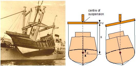 Figure 1.4: Lifting the Santa Maria replica with possibly unstable suspension The lifting arrangement in Figure 1.4 shows the typical short height v of the primary suspen-sion of the transverse beams at that time. The precise vertical position of the centre of gravity of the replica hull was certainly not known. The metacentric height h of this arrangement may be calculated by:
h = metacentric height [m] It appears that the metacentric height of the arrangement is very small or even negative. It therefore remains uncertain whether the tilt of the replica hull results from a very small transverse offset of the centre of gravity or from a negative value of the metacentric height h. In any case the pressure from the slings on the low side of the hull stabilised the arrangement. 1.2.2 Lifting a nuclear reactorThe lifting arrangement for a 360 t unit in Figure 1.5 shows the same short distance v as in the previous case. The arrangement hangs straight, either because the metacentric height is still positive or by the stabilising effect from the contact of the secondary slings to the body of the cargo unit. The metacentric height h may be obtained by the same formula as under case 1.2.1 above.
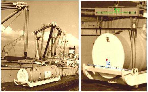 Figure 1.5: Lifting a nuclear reactor, close-up of centre of gravity and centre of suspension 1.2.3 Lifting a catamaranThe lifting arrangement in Figure 1.6 has a greater distance v due to the sling connection from the hook to the lifting beam. But there is also a great distance z creating the risk of a very small or even negative metacentric height of the suspension. The unit did not hang straight and was only stabilised by sling contact. There was no damage to the hull due to the use of soft slings in the secondary suspension. The metacentric height h of the suspension arrangement may be obtained by the formula:
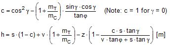
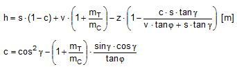
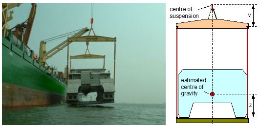 Figure 1.6: Lifting a catamaran hull, estimated centre of gravity 1.2.4 Arrangement with inclined secondary slingsThe arrangement in Figure 1.7 shows inward inclined secondary slings. Although the height of the primary suspension v is quite large compared to the elevation of the centre of gravity z, the metacentric height of the arrangement is only about 1 metre due to the inward inclined secondary slings. For inclined secondary slings the metacentric height h of the arrangement must be obtained by an extended set of formulas:
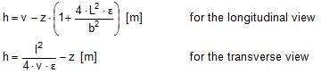
h =metacentric height [m] The estimated parameters in this case are: v = 3.6 m, s = 7.5 m, z = 1.1 m, f = 26°, g = – 4°, mT = 2 t, mC = 60 t Results: c = 1.14256, h = 1.0 m 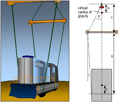 Figure 1.7: Arrangement with inward inclined secondary slings, estimated parameters This arrangement is quite sensitive against negative angles g due to the large distance s. An angle g = – 6° would already create a negative metacentric height. 1.2.5 Dual crane lift with primary suspensionFigure 1.8 shows a dual crane lift with purely primary suspension. Such suspensions are stable as long as the centre of gravity of the cargo unit is below the centre of suspension. The range of stability depends on the width of the slinging base of the unit. The metacentric height of the suspension would normally be calculated by h = (v – z) metres in the longitudinal view, while an unlimited metacentric height is assumed in the transverse view. However, the stability of such arrangements may be impaired by the flexibility of the slings, because a small offset of the centre of gravity, e.g. to the left, will tilt the arrangement to the left with load increase in the left slings and decrease in the right slings. The resulting changes in length will cause an additional tilt to the left, which may be arithmetically expressed as being induced by an elevated centre of gravity. 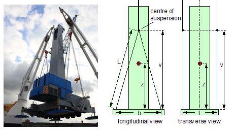 Figure 1.8: Dual crane lift with primary suspension, essential parameters The relative elongation at reaching their lifting WLL may be attributed to soft slings with e = 0.023 (= 2.3%) and to wire rope slings with face=“Symbol“>e = 0.004 (= 0.4%). The formulas for obtaining the metacentric heights are given in chapter 1.3 below. Estimated parameters in this case are: L = 15 m, v = 14.5 m, b = 7.7 m, l = 5.9 m, z = 8.4 m, e = 0.023 (Polyester), e = 0.004 (Stahl)
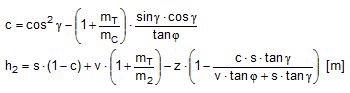
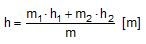
The results show satisfactory figures in all cases, but this may change quickly with other parameters, in particular with smaller values of b and l. 1.2.6 Dual crane lifts with primary and secondary suspensionFigure 1.9 shows three versions of suspension arrangements with identical overall slinging height but different shares of primary and secondary suspension. The level at M indicates the centre of suspension, while G* is the virtual centre of gravity. The metacentric height decreases with the share of the height of the primary suspension. The arrangement on the right side is definitely unstable. This leads to the design rule: In a given slinging height the share of the primary suspension should be as large as possible. 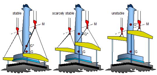 Figure 1.9: Different shares of primary and secondary suspension 1.2.7 Dual crane lift with dramatic capsizeFigure 1.10 shows the result of insufficient suspension stability in the unloading operation of a fully rigged mobile crane in 2010. The metacentric height was obviously marginal and the capsize took place shortly before landing the unit on the jetty. The cause could have been a slight upcoming wind catching the large outrigger of the mobile crane. Gladly no persons were injured. A new crane had to be ordered. 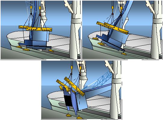 Figure 1.10: Capsize due to insufficient metacentric height of suspension arrangement 1.2.8 Single crane lift with asymmetric suspension arrangementFigure 1.11 shows an asymmetric suspension arrangement for lifting a heavy dumper truck. The forward suspension consists of a single vertical wire rope grommet that is fastened to a lift point below the centre of gravity of the truck. This forward suspension is definitely unstable with a negative metacentric height h1 = – z, as shown in the schematic drawing. The rear suspension consist of a primary and a secondary suspension. The level of lift points is apparently above the centre of gravity, producing a negative value of z with regard to the convention of signs used in this paper. The secondary suspension angle g has also a negative value. The metacentric height of the rear suspension is obtained by the formulas:
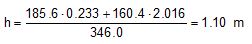
The common metacentric height is obtained by:
h = common metacentric height [m] Results: c = 1.12764, h2 = 3.05 m
The overall suspension is sufficiently stable. 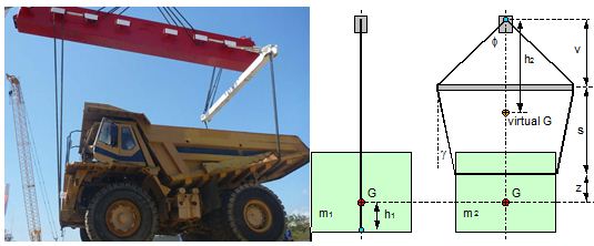 Figure 1.11: Asymmetric suspension arrangement 1.2.9 Dual crane lift with asymmetric suspension arrangementFigure 1.12 shows a dual crane lift with an arrangement where the centres of suspension and also the virtual centres of gravity of the partial masses are situated in different levels. The common centre of suspension as well as the common virtual centre of gravity may be obtained graphically. This is shown in Figure 1.13. 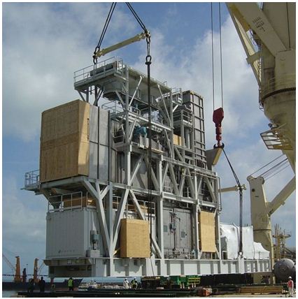 Figure 1.12: Dual crane lift with asymmetric suspension arrangement The metacentric heights of the forward and the rear suspension and the common metacentric height are obtained by the same formulas as used in the previous example. The necessary parameters have been estimated with fairly good accuracy as follows:
The unit hangs stable, yet the stability margin is small. It could have been improved by elongating the primary suspension on the right side. A capsize was impossible due to the stabilising effect of the long secondary slings contacting the cargo unit. 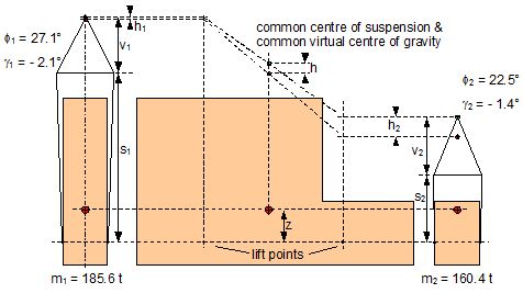 Figure 1.13: Graphical determination of common metacentric height Top of page 1.3 Assessment toolsThe stability of a suspension arrangement should be assessed, whenever the lift points on a cargo unit are below its centre of gravity. The relevant formulas for assessing a planned arrangement are given below for quick reference. 1.3.1 Primary slings onlyFigure 1.14 shows the relevant parameters for assessing a suspension with primary slings only. It should be noted that for reasons of clarity a symmetrical arrangement is assumed. 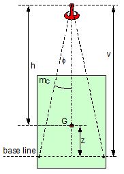 Figure 1.14: Parameters of a primary suspension Metacentric height h = v – z [m] Note: z is negative if G is below the base line. If the angle f < 5° AND z > v × tanf, the arrangement is close to a situation where a small disturbance by wind or swell may overwhelm the stability. It is therefore prudent to treat this suspension as a single sling attachment with the pivot at the lift point, unless special precautions are taken to stabilise the hanging unit. Otherwise, the metacentric height is: h = – z [m] Use of soft slings Soft slings have an elongation that is about 6 times greater than that of wire rope slings, both at reaching their respective WLL. This is characterised by the figures of relative elongation for soft slings of e = 0.023 (= 2.3%) and for wire rope slings of e = 0.004 (= 0.4%). These figures should be taken as indicative values only. They may vary in practice. 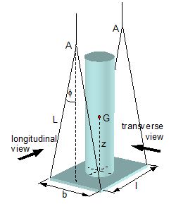 Figure 1.15: Assessment of metacentric height when using soft slings The metacentric height of such arrangements should be assessed according to the explanation in chapter 1.2.5 by extended formulas:
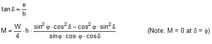
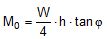
h = metacentric height [m] Range of stability The range of stability of a primary suspension may be demonstrated by the righting moment of the sling on one side as a function of the tilting angle d. Such a tilting angle may appear as the result of a transverse offset e of the centre of gravity of the cargo unit.
The initial righting moment in the upright hanging condition with d = 0 is:
d = tilting angle [°] 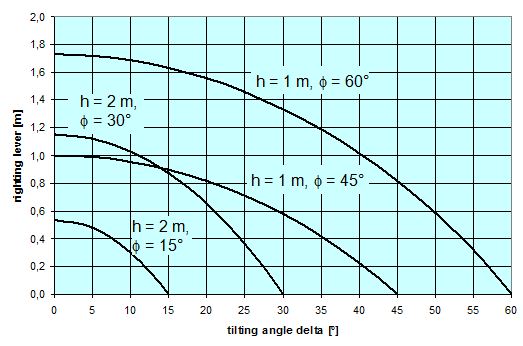 Figure 1.16: Range of suspension stability 1.3.2 Primary and secondary slingsFigure 1.17 shows the relevant parameters for assessing a suspension with primary and secondary slings. 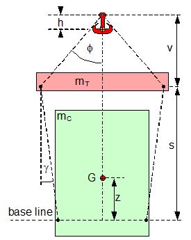 Figure 1.17: Parameters of a primary and secondary suspension Metacentric height
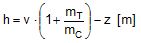
The formulas for obtaining c and h are inconvenient and prone to typing errors in manual computer calculation. It is therefore recommended to apply a simple Excel sheet as shown below. The green shaded cells are entry data, the orange shaded cells contain the results. 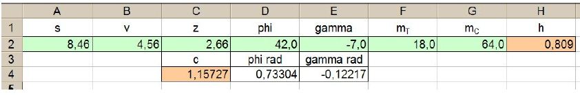 c: C4=cos(E4)^2-(1+F2/G2)*sin(E4)*cos(E4)/tan(D4) If the secondary suspension is exactly vertical, i.e. angle g = 0 with c = 1, the formula for the metacentric height is simplified to read:
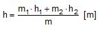
Soft slings The use of soft slings in a combined primary and secondary suspension will create similar impairment to the metacentric height as shown for pure primary suspensions. It is therefore recommended not to use soft slings in such combined arrangements, unless an ample figure of positive metacentric height can be verified. 1.3.3 Asymmetric suspension arrangementsIn case of asymmetric arrangements the suspension on both ends of the cargo unit should be analysed separately with the results of the partial masses m1 and m2 and the associated metacentric heights h1 and h2. The common metacentric height is obtained by:
h = common metacentric height [m] |
|
Top of page
| Contents
| |