
|
Tipping balance of transversely and diagonally stowed cargo units Prof. Hermann Kaps, Peter van den Berg |
[German version] | ||||||||||||||||||||||||||||||||||||||||||||||||||||||||||||||||||||||||||||||||||||||||
|
The Annex 13 of the CSS-Code has elsewhere under „tis-gdv.de“ been characterised as a „broadly applicable testing method, which balances the forces and moments acting on a cargo unit or cargo assembly with the strength capacity of the employed securing devices“. In special cases, this broad applicability can only be achieved through competent interpretation by the user, since an international guideline like the CSS-Code cannot cover all specialities beyond principles. This article highlights such special cases and provides their solution. Cargo units of a „longish“ character, i.e. longer than wide, typically will be stowed on board a cargo vessel in an orientation which is either called „longitudinal“ or „transverse“ related to the ship’s body. In the first case, that is longitudinal stowage, a risk of tipping would, if at all, exist in transverse direction, in the second case in longitudinal direction. The first case is by far predominant, which is why a transverse tipping balance, using the transverse force Fy, has been explicitly outlined in Annex 13. 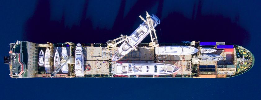 Figure 1 : Cargo stowed in longitudinal and transverse orientation The second more uncommon case of longitudinal tipping relating to transversely stowed cargoes, has not been described in Annex 13. The longitudinal tipping balance, however, cannot be replicated one-to-one from the transverse tipping balance. Instead, in analogy to the longitudinal sliding balance, a reduced weight of the cargo must be assumed due to an upward vertical force Fz. This is a logical consequence based on the above mentioned competent interpretation. The Annex 13, in fact, requires that in all balance calculations the most unfavourable combination of horizontal and vertical forces is to be assumed. In transverse balances the worst case comes with concurrent weight increase, which amplifies the horizontal force induced by the large presumed roll angle (down-hill force), whereas the normal force perpendicular to the deck is abated by the same roll angle to about the normal weight. This is then used in the transverse balances for friction and the inherent stability moment of the cargo unit, which depends on its own weight and the width of its base. Pitching angles are much smaller than rolling angles. Therefore the composition of the expected longitudinal acceleration is structured differently. Here the worst case in longitudinal balances appears with concurrent weight decrease. This happens for example on a pitching vessel, where the bow, after reaching the highest position, comes down again and the cargo in the whole forebody of the ship appears to be lighter. This does not only reduce bottom friction, as reflected in the sliding balance, but also the inherent stability moment of the cargo, which – in a tipping balance – is an important safety asset. The difference between the external tipping moment and the inherent stability moment presents the minimum demand of additional securing measures against tipping by means of lashings or vertical stoppers. In analogy to that in transverse direction, the external longitudinal tipping moment is compiled using the calculated longitudinal force including forces from wind pressure and „sea sloshing“ and the tipping lever „a“. For usual compact cargo units Annex 13 simply allows those three combined forces to act in the centre of gravity of the cargo. But for particularly high units, where the centre of the wind exposed surface is distinctly located above the centre of gravity of the unit, the wind force should be calculated acting in its realistic centre. 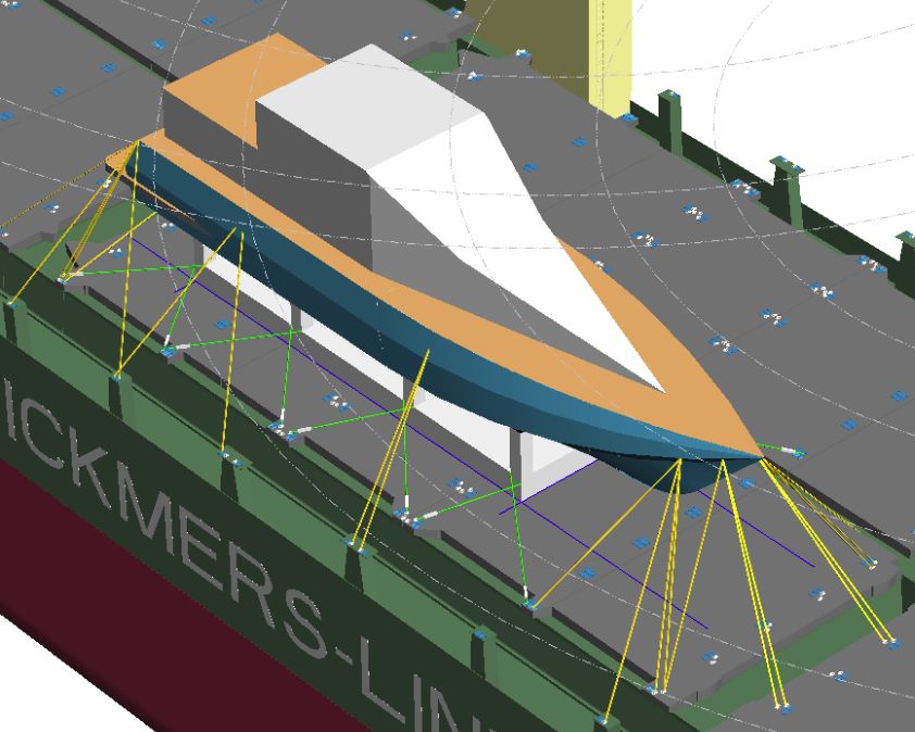 Figure 2 : Longitudinal stowage 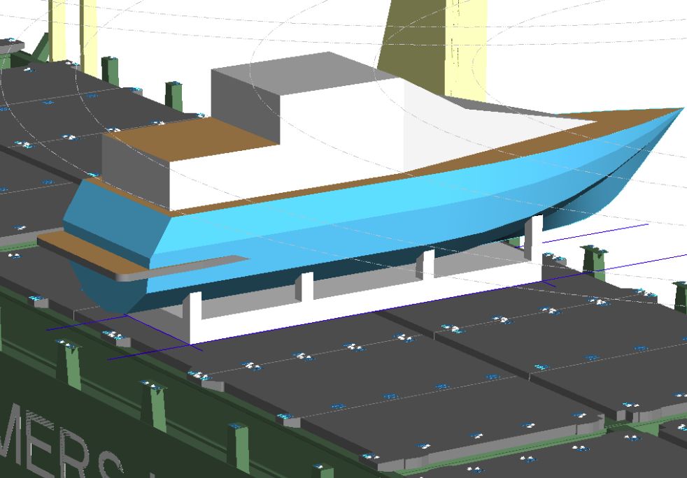 Figure 3 : Transverse stowage Having outlined the tipping balance in the ship’s longitudinal direction and together with the transverse tipping balance, as provided by the Annex 13, now also cases can be evaluated where a „tipping-sensitive“ cargo unit – for any operational reason – is planned or has been stowed diagonally on top of the hatch covers of a cargo vessel. This challenge is the key-topic of this article. How should this be solved? A diagonal stow has, by the way, no influence on the examination of sliding. Both balances for transverse and longitudinal sliding are compiled and if found satisfactory, sufficient sliding resistance can be assumed for any other direction. This is not the case with tipping. If a cargo unit tips, it turns around a tipping axis. This axis is fairly determined by the bedding construction and the position of the cargo „footprint“. It thereby defines the direction of tipping, the acting moments and finally the securing demand. This applies also for diagonally stowed cargo. 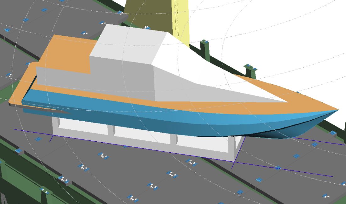 Figure 4 : Diagonal stowage with δ = 30° 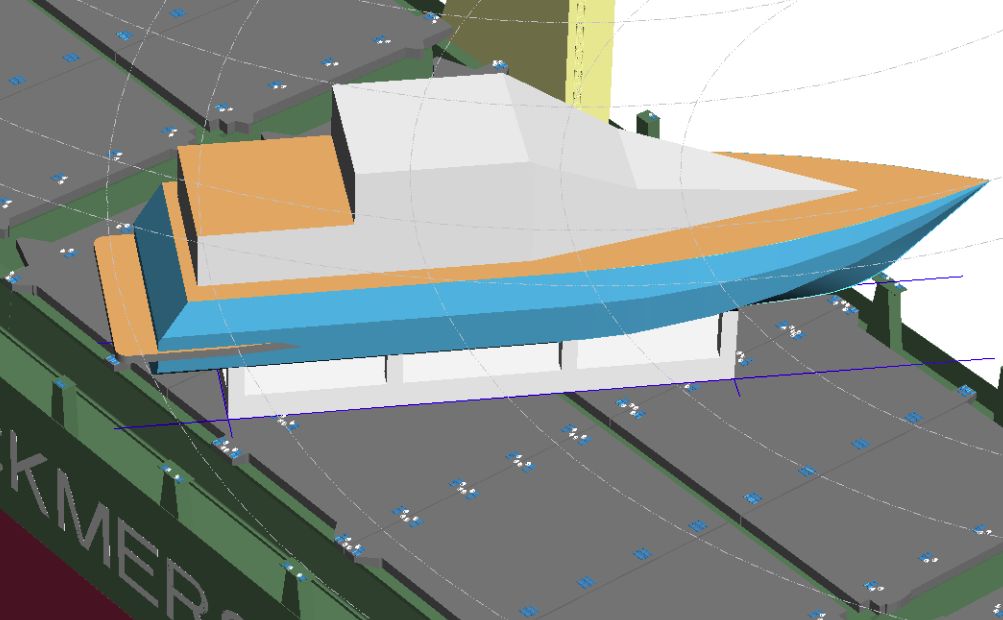 Figure 5 : Diagonal stowage with δ = 60° The pragmatic interpretation of Annex 13 for this purpose, and finally the practical solution, consists of determining the minimum securing demand for transverse tipping (virtual longitudinal stowage) and for longitudinal tipping (virtual transverse stowage) separately. The actual minimum securing demand against tipping will then be interpolated between these two results, dependent on the angle of diagonal stowage. For this interpolation a smooth, rounded transition between the two reference values is assumed. For that purpose a simple formula is available and that’s it. But to make it more understandable and memorable, a calculated example is presented, referring to the pictures of the motor yacht shown above.
Remark: As the yacht, independent of her stowage direction, may only tip crosswise to her keel and the bedding structure is symmetrical, there is only one figure for „a“ and also one figure for „b“, which rotates with the stowage direction of the yacht and is related to her coordinate system. Any tipping of the yacht in the direction of her keel can be excluded due to the length of the cradle.
Remark: The above surfaces of the cargo are also given in the coordinate system of the cargo unit. Annex 13 states: Wind pressure pw = 1 kN per m2, „sea sloshing“ ps = 1 kN per m2. Allocation and orientation of the cargo:
Mt Moment against tipping = Minimum securing demand against tipping Longitudinal stow:
Minimum securing demand against tipping for longitudinal stowage:
Transverse stow:
Mindestbedarf an Kippsicherung bei Querstau:
Minimum securing demand against tipping for diagonal stowage at angle δ:
The securing arrangement against tipping, in particular lashings, posts or welded stoppers with clips against lifting, must have at least the capacity of 971 kN⋅m. A suitable orientation of the dedicated securing devices with regard to the tipping axis should be observed. 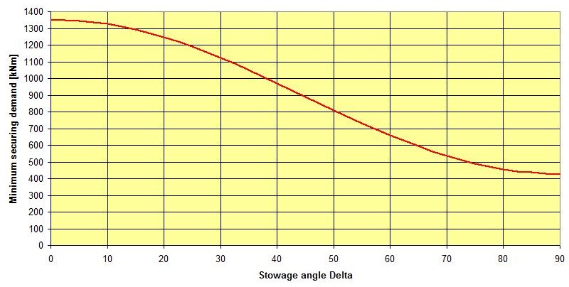 Figure 6 : Interpolation between transverse and longitudinal securing demand | |||||||||||||||||||||||||||||||||||||||||||||||||||||||||||||||||||||||||||||||||||||||||
| Seitenanfang | |