
| Photo of the month – February 2003 | [German version] |
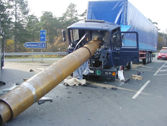
Figure 1 [Johann Ridder]
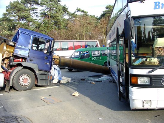
Figure 2 [Johann Ridder]
"Everyday madness" – steel pipes as projectiles
While driving onto highway 31 from a main road in the Wesel district, a coach carrying school children failed to notice an oncoming articulated truck. The truck driver slammed on the brakes to avoid colliding with the coach.
The truck was loaded with three steel pipes inserted one inside another with a gross weight of 17 metric tons. It is not known how or whether the load was secured. What is certain is that the securing measures were inadequate as the deceleration was enough to make the pipes shoot forwards, crash through the trailer headboard and driver’s cab before finally embedding themselves in the ground just in front of the coach’s rear axle.
Almost unbelievably, the truck driver was only slightly injured, while the 58 children got away with a bad fright. The outcome could well have been fatal for some of them.
How can a load like this be sensibly and economically secured?
Transporting the pipes inserted one inside another unnecessarily complicates load securing.
It should be checked whether it is also possible to transport them side by side or in the cantline. If so, the pipes may effectively be secured as proposed in the following drawing:
In the following example, it is assumed for simplicity’s sake that the three pipes are all of identical weight and identical diameter.
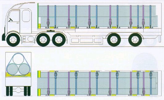
Figure 3
Figure 3 assumes that the semitrailer’s headboard is reinforced and is capable of bearing such forces. In the remaining explanations, it is assumed that a reinforced headboard is not available.
The pipes are laid on rectangular wooden planks arranged perpendicular to the direction of travel on the vehicle floor. Non-slip mats are laid between the loading area / wooden planks / load. A non-slip mat must also be used if a pipe is transported in the cantline. In order to prevent the pipes from rolling during loading, pipe wedges should be placed on the wooden planks. When loop lashings are used, the required number of lashings should be determined beforehand.
For the purposes of the following calculations, the pipes are assumed to have an individual mass of 6 metric tons, while the friction on the non-slip mat is assumed to be µ = 0.5. Elevated loads may bring about physical changes to the non-slip mats which have a negative effect on their friction coefficients; information about such changes should be obtained from the manufacturer.
Sideways securing: If, instead of being transported side by side, the pipes are transported in the cantline, it must be ensured that the securing used can withstand the transverse forces (see Figure 4). When transporting pipes loaded in the cantline, unlike those loaded side by side, it must be borne in mind that cylindrical items of identical diameter loaded in this manner generate elevated transverse forces as a function of the bearing angle. The left hand side of Figure 4 shows the distribution of forces in „abutting“ cantline loading. In this case, the transverse force generated amounts to 30% of the weight-force of the pipes. In the present case, this means that a 6 metric ton pipe loaded in the cantline will produce additional transverse forces of approx. 1,800 daN on each side (6 metric tons x 30%). The 1,800 daN force is secured by loop lashings, as calculated below.
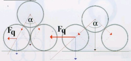
Figure 4
Securing the load against sideways acceleration: Since there is negligible rolling friction between round items, friction is assumed to make a zero contribution to sideways securing and a value of 0.5 g is thus applied. In other words, 50% of the load weight must be secured against sideways acceleration.
For all three pipes (18 metric tons x 0.5 g = 9,000 daN per side), at least three loop lashings must be used on each side, as a single loop lashing has a maximum lashing capacity (LC) of 4,000 daN. This takes account of the fact that most vehicles only have load securing points with an LC of 2,000 daN; providing that the load securing points are arranged close together as in Figure 3, the resultant angles can be disregarded as they have only a very slight impact on LC. Care must be taken to ensure that different load securing points are used.
Once the pipes have been loaded, the loop lashings, which had been arranged on the vehicle before loading, are fastened.
Forwards securing: Each individual pipe must be provided with 0.8 g, i.e. with 80% of its weight-force, of forwards securing. The friction, which acts against any slippage, may be subtracted from this value. As described above, friction is assumed to have a value of µ = 0.5 (50% of weight-force). 30% of the weight-force thus remains to be secured. In other words 0.3 x 6,000 daN = 1,800 daN per pipe; a securing force of 1,800 daN per pipe must accordingly be applied.
On the assumption that, due to their dimensions, the pipes will be transported in the cantline (c.f. Figure 3) and that the semitrailer does not have a reinforced headboard, only the bottom two pipes can be loaded against the headboard. For this purpose, rectangular beams must be laid in front of the headboard to distribute the pressure. The two pipes must be loaded absolutely tightly against (in direct contact with) these rectangular beams. Assuming that the headboard can withstand a load of 5,000 daN and the headboard’s securing force is evenly distributed between the bottom pipes (5,000 daN / 2 = 2,500 daN), the bottom layer does not require additional securing. The pipe lying in the cantline must not bear on the trailer headboard; it could be secured by a loop lashing around the „head“ of the pipe or by individually securing the head of the pipe directly to a load securing point. It would have to be possible to hook at least one belt (preferably two) directly onto the pipe edge (c.f. Figure 5). The hook may have to be padded so as to cause no damage.
Figure 5
Care must be taken to ensure that the belt is passed as straight backwards as possible to a load securing point, as the greater is the angle to the side, the smaller is the forwards securing force exerted by the belt. Given an LC of 2,000 daN and a 1,800 daN shortfall in securing force, the angle to the side must be no greater than approx. 25° (cos alpha = 1,800 daN / 2,000 daN). If no suitable load securing points are available in this favorable position or if this relatively small angle cannot reliably be measured on the vehicle, two belts per pipe must be used.
If, for reasons of load distribution, the pipes are loaded with a gap between them and the headboard, this gap must be filled with lumber or forwards securing must be provided with loop lashings around the head of the pipes or with direct lashings hooked into the pipes. When using loop lashings, care must be taken to use suitable protectors to protect the belts from the sharp edges of the pipe ends.
If it is essential to transport the pipes inserted one inside another, the following securing method can be proposed:
The pipes must be loaded with a gap between them and the headboard. Securing to the sides is provided as described above. At the head of the pipes, a rectangular beam is laid longitudinally in the direction of travel beside the pipes on each side. A stack of two or three rectangular beams is laid in front of the pipes, perpendicularly to the direction of travel, on top of the longitudinal rectangular beams. The beams should be laid in pairs one beside the other and be of a sufficient height that they also cover the inner pipe with at least one beam thickness. Loop lashings must now be applied around this stack of beams as shown in Figure 6.
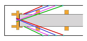
Figure 6
On the assumption that the load securing points have an LC of 2,000 daN and that each belt is attached to two different load securing points, a total of four loop lashings must be used to provide forwards securing. Four loop lashings thus supply a securing force of 16,000 daN. The angle of spread results in a loss of securing force of at most 10-20%, meaning that, in the most unfavorable circumstances, a securing force of 12,800 daN remains. It must be ensured that the vehicle used has sufficient load securing points as this form of securing in conjunction with the sideways securing described above requires numerous load securing points since, if the full LC of the belt is to be utilized, only one belt end should be attached to each securing point.
When calculating the necessary total securing force, it must be borne in mind that in this type of securing, only the outer pipe is secured on non-slip mats with a friction of µ = 0.5, while the inner pipes only have a friction of µ = 0.1 (steel on steel).This means that the outer pipe is provided with 3,000 daN of frictional securing and the inner pipes are secured by twice 600 daN. Friction thus only supplies 4,200 daN of securing force.
The load securing measures must provide a securing force of 10,200 daN (3 x 6,000 daN x 0.8 = 14,400 daN minus 4,200 daN).
In the latter securing example, it must also be ensured that all the individual pipes are in direct contact with the stack of beams.
Forwards and sideways securing require a total of 10 load securing points on each side, each point only being capable of accommodating a single belt, with the exception of those points providing forwards securing which can also accommodate a belt providing securing to the rear. If not enough load securing points are available, it must be checked whether the loop lashings can be fastened to the chassis. In this case, it must be ensured that the load securing materials are equipped with claw hooks. If the vehicle is not appropriately equipped, it is unsuitable for carrying pipe loads.
When providing securing to the rear, it must be checked whether all the pipes are of the same length. Should the inner pipes be shorter, appropriate wooden structures must be provided so as to ensure a tight fit to the rear as well. Securing may then be provided in the same way as the forwards securing. If the inner pipes are longer, the pipes must be directly secured so as to prevent them from slipping backwards.
Back to beginning