
| Photo of the month – March 2017 |
[German version] |
Torpedo tubes
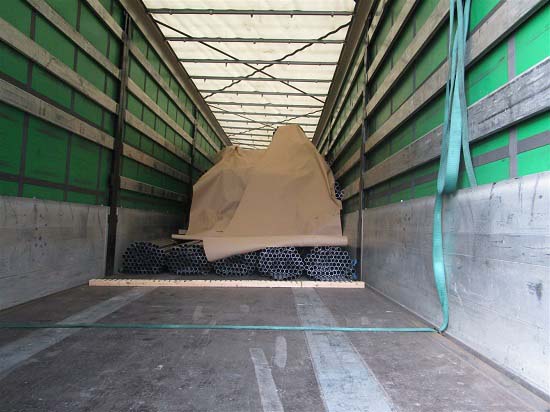
Figure 1 [Jaspers, Wolfgang]
This load, comprising 23.5 tonnes of bundled steel tubes or pipes arrived from Italy as an intermodal consignment and was picked up by the tractor unit from the Köln-Eifeltor terminal. When questioned, the driver said that he had checked and re-tensioned the load-securing equipment, which comprised 10 2500 daN belts with an STF of 500 daN, and then set off.
On reaching the end of a tailback, the driver, clearly as a result of a lapse of concentration, had to brake sharply, causing the load to slip forwards. Figure 1 clearly shows that, for reasons of load distribution, the majority of the load had been placed in the two middle quarters of the loading bed as delineated by the stanchions. The fact that there is a rectangular piece of lumber on the loading bed with no contact to any part of the load strongly suggests that the load had originally protruded significantly into the fourth quarter of the loading bed. In fact, the bottom layer of the load is clearly in the third quarter and the top part of the load has slipped a lot further forward.
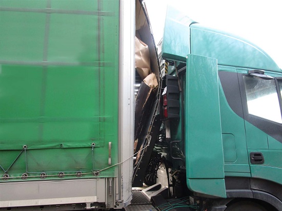
Figure 2 [Jaspers, Wolfgang]
Figure 2 shows how the kinetic energy of the load was converted to deformation energy. To put it bluntly, the end wall was almost completely separated from its frame. We shall discuss the fact that the tarpaulin lace or the customs seal string is still hooked in somewhere on the end wall when we look at Figure 4.
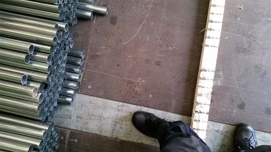
Figure 3 [Jaspers, Wolfgang]
In Figure 3 we can see the last piece of dunnage, which has clearly not moved forward. The only thing that moved was the load. In Figure 1 we already clearly saw that the top part of the load slipped significantly further than the bottom layer. The bottom layer (the end of which we can see in Figure 3) was originally resting on the rectangular dunnage. The marks left on the dunnage by the slipping steel pipes could indicate that the pipes had been oiled, as the black marks that may have been caused by corrosion products being rubbed off by friction, could equally well be staining from anti-corrosion oil. Furthermore, there are a number of oil stains on the loading bed, as we can see in Figure 5.
Figures 4 and 4a [Jaspers, Wolfgang]
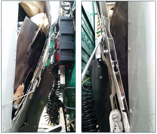
Figures 4 and 4a show the end wall from the right of the vehicle and the left of the vehicle respectively. On both sides we can see that a belt has been tensioned across the front of the end wall. The customs seal string or the tarpaulin lace has been fastened to the ratchet tensioner of the right-hand belt, although we cannot imagine why this has been done. Either the driver had intended to continue his journey with the damaged vehicle or the trailer was already damaged when he took it over and he had tried to use the two belts to at least push the end wall back a little. Or perhaps he was in the process of restoring his vehicle to what he thought was a "roadworthy" condition after the accident in order to continue the journey.
Comment from a reader
+++++++++++++++++++++++++++++++++++++
I just had a look at the Photo of the Month and have a difficulty with your explanation of the belts at the end wall. In our company, we have similar semitrailers where it is possible to open the sliding cover from the front. To prevent the mechanism from opening inadvertently, belt buckles are fitted to the left and right of the end wall. These accommodate the belts that are attached to the tarpaulin. Looking at the pictures, I suspect that the trailer in the accident was using the same system, as it appears very similar. (Dominik Sinovzik)
+++++++++++++++++++++++++++++++++++++
Thank you for this constructive comment!
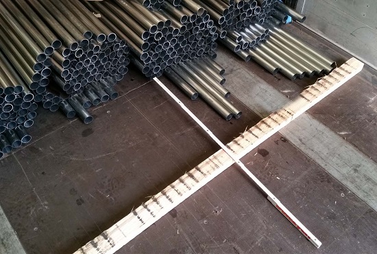
Figure 5 [Jaspers, Wolfgang]
Figure 5 clearly shows that even the base of the load has probably slipped forward by at least 80 cm and that the bottom part of the load has slipped forward by around 2.5 – 3 m. If the packages at the top of the load were shorter, which is not something we can see clearly on the photos, they have not slipped as far as the rear face of the load would lead us to believe.
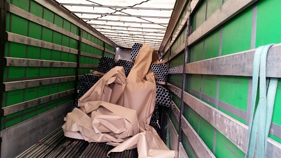
Figure 6 [Jaspers, Wolfgang]
Figure 6 shows the intermediate wooden dunnage and some crumpled paper that had originally been laid neatly over the load. This paper may have been intended to keep any atmospheric condensation that collected on the tarpaulin roof during the cool night from the susceptible steel. We would have liked to see this amount of care taken when securing the load. Because the load is made up of steel pipes bundled with steel straps, and the resulting bundles are almost round in cross-section, the bundles had to be separated by intermediate wooden dunnage to compensate for the bilge and cantline effect*.
Bilge and cantline stowage generates additional lateral forces that in turn have to be countered with additional load-securing measures. Furthermore, the additional pressure on the load has a damaging effect.
*Bilge and cantline stowage is the result of cylindrical loads being stacked. This generates additional lateral forces. We can see these forces at work with a simple demonstration that can be done at any desk. Simply place two round pencils next to each other on a desk so that they are touching and then place a third exactly in the middle. The result is that the additional forces push the two bottom pencils apart. If you now place two matchsticks across the bottom two pencils and try again, it is possible to stack the third pencil on top of the other two.
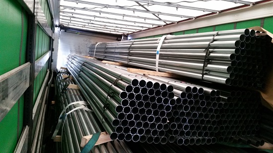
Figure 7 [Jaspers, Wolfgang]
Figure 7 clearly shows the intermediate wooden dunnage. Below the top layer of the load, all the dunnage that had originally been placed on edge has tipped over and is now lying flat under the load. No further load-securing measures can be seen. All the lashing belts are lying loose across the load.
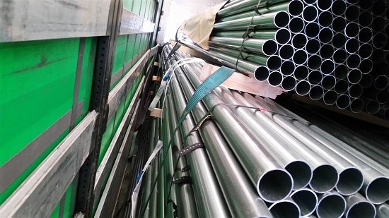
Figure 8 [Jaspers, Wolfgang]
Only in Figure 8 can we with difficulty make out a torn belt on the loading bed on the bottom left. And Figure 8 also clearly shows that the last piece of dunnage in the second layer from the top has already broken. This shows not only that low-grade lumber was used (knots), but also that the lumber was clearly too weak, as the dunnage was probably placed on edge deliberately in order to withstand the pressure of the load better. But if tie-down lashings are used to secure the load, dunnage that is placed on edge completely eradicates any load-securing effect, as it can tip over at the first movement.
The fact that all the belts are simply hanging loosely over the dunnage ought to indicate that they have all torn. But given that the load slipped by some 2.5 – 3 m, they ought to be lying on the loading bed and not neatly over the dunnage. We have no coherent explanation for this observation.
Load securing
An attempt was clearly made to secure the load with tie-down lashings, which makes little sense for smooth steel pipes, which may even have been coated in oil. And it makes even less sense when only lumber was used during load securing, rather than anti-slip mats. It would appear that braided or similarly prepared anti-slip tapes were used between the individual layers of pipes. We do not know whether these tapes were intended to separate the pipes from each other to avoid abrasion or whether the rubber tapes (which were probably made of anti-slip material) were also intended to increase the level of friction within the bundles of pipes.
Assessment of load securing
Because this vehicle was an intermodal consignment, traveling both by rail and by road, the load securing measures should have complied with the requirements for intermodal transport, i.e.1 g acceleration in both directions, and with the requirements for road transport, namely 0.8 g to the front and 0.5 g to the sides and to the rear. It goes without saying that the load-securing measures used here, if they did in fact comprise 10 tie-down lashings, did not anywhere near meet these requirements. A load with a weight force of 23,500 daN requires a total securing force of 18,800 daN for transportation by road. If the pipes were coated with oil, a coefficient of friction μ of 0.2 would probably represent a recklessly high figure. At a coefficient of friction μ of 0.2, a securing force of 14,100 daN would still be required. If we assume that all 10 belts were actually pre-tensioned to an STF of 500 daN and that the round, smooth shape of the load meant that there was no loss of friction over the load, we would have a total pre-tensioning force of 10,000 daN. Because the belts ran almost vertically, the angles involved have no impact or only a negligible impact. If we multiply this pre-tensioning force of 10,000 daN by the coefficient of friction μ of 0.2, we get a securing force of 2000 daN. We then have a total shortfall in securing force of 12,100 daN. Even if we assume that the pipes are not coated in oil, we would take a coefficient of friction μ of 0.4, which would leave a shortfall in securing force of 5400 daN. In this case, these securing calculations are entirely pointless, as the topmost dunnage of the load had tipped over, thus eliminating any tie-down effect (pre-tensioning force).
The right way to secure the load
We assume that this load comprised oil-coated steel pipes. We want to examine how to secure the load on the basis of friction and on the basis of direct lashings.
Securing on the basis of friction
Rectangular cross-section dunnage such as the dunnage we saw on the loading bed must be used. All the layers must be separated from each other in such a way that the bundles of pipes can be picked up by cranes or forklift trucks without difficulty. In other words, the rectangular dunnage must be thick enough, and a sufficient quantity or sufficiently thick dunnage must be used to ensure that the dunnage in the bottom layers is also able to bear the load of the top layers. The top and bottom of all the rectangular dunnage must be covered with anti-slip mats. Ideally, these should be glued or secured in some other way. If the anti-slip material has been tested by the trade association or other body, it must be capable of delivering the certified level of friction when contaminated with oil. We can therefore assume a coefficient of friction μ of 0.5 or even 0.6, even in the case of oil-coated pipes. If we take a coefficient of friction μ of 0.6, additional securing measures would have to deliver a securing force of 4,700 daN. If we return to our 10 tie-down lashings, each delivering 1000 daN of pre-tensioning force that is acting vertically, this provides a total of 6000 daN of securing force. In other words, under these particular circumstances, it would be possible to secure this load by friction even if the pipes were coated in oil. The only uncertainty in using tie-down lashings to secure the load is the internal friction within the bundles of pipes. As we can see clearly from Figure 5, the load has slipped against itself, which means that we would prefer direct securing of this load.
Direct securing
Preparations for direct securing are identical to those for friction securing. Again, rectangular cross-section dunnage is covered with anti-slip material, which should preferably be glued. The bundles of pipes are loaded as a tight fit against each other, and are secured to the sides with two loop lashings from each side. jThese four loop lashings provide a sufficient minimum securing force to secure the load to the rear by means of friction. Securing the load to the front requires considerably more effort. Because there is a risk that the bundles of pipes will slip internally, each layer of bundles must be "covered" by 3 or even 4 pieces of squared lumber. These pieces of squared lumber allow loop lashings to be placed appropriately. Depending on the lengths of the packages, it is possible to make sure that each layer is loaded slightly further back (approx. 10 cm) to ensure that the stacked squared lumber finds purchase. If insufficient squared lumber is available to cover the end faces of the bundles of pipes, it would also be possible to secure the loads using pallets through which two pieces of squared lumber had been passed. Two loop lashings could be used to secure three pallets placed vertically next to each other and through which two pieces of squared lumber had been passed across the entire width of the vehicle. This would cover two layers of pipe bundles. The same procedure is then used in the next layers. If it is also possible to load the bundles behind each other, this reduces and simplifies the work involved.
Your load securing columnists as always wish you a safe journey!
Back to beginning