
| Photo of the month – September 2015 |
[German version] |
Smart securing
Loading beds are there for transporting loads. And this double-cab flatbed was built last century for exactly the same purpose. But the vehicle was also designed for carrying people.
The primary target group was tradespeople who wanted to take their tools and materials with them to the site. Undoubtedly, nobody ever thought that it would be used for transporting a vehicle.
Even a small car such as the one we can see in Figure 1 is too long for the loading bed, which is around 1.90 m in length. It is patently obvious that it appears to be standing on the open rear tailgate:
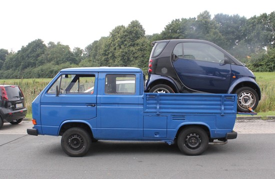
Figure 1 [Jan Bode]
And the center of gravity is another question that we should address here. The rule of thumb is that a load's center of gravity should always be in the middle of the loading bed. And the photo suggests that this may just be the case. So why is the rear of the vehicle riding so low?
This could be something to do with the weight of the load. The Smart has a curb weight of around 800 kg. If we assume that the Transporter has a curb weight of around 1450 kg, the rear axle would be carrying more than 700 kg without the vehicle being loaded. This would mean that, together with the load the vehicle was carrying in this case, the rear axle was bearing more than 1500 kg.
The permitted rear axle load is around 1300 kg, which means that the vehicle is overloaded. This provides an initial explanation of why the vehicle is riding so low.
The second explanation can be found if we take a look under the vehicle. The right-hand rear shock absorber is not connected to the axle and is just hanging loose, where it can have no effect (See Figure 1.1). But we shall not discuss that any further here.
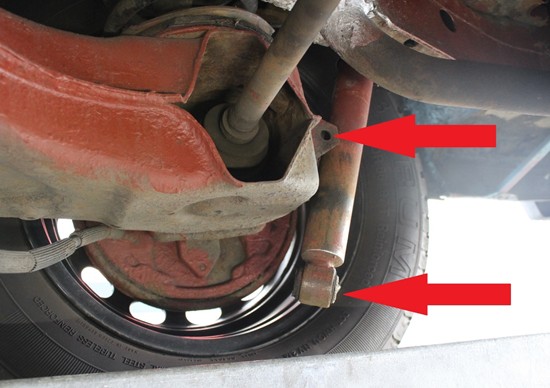
Figure 1.1 [Jan Bode]
We are here to discuss load securing.
If we have a look at the vehicle from the back, it would seem that the rear tailgate is a loading ramp. Which it isn't. It is hanging virtually freely, supported only by a wire rope and a belt:
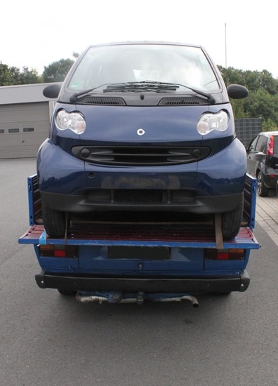
Figure 2 [Jan Bode]
The belt and wire rope are both attached to the axle of the Smart. They have been taken round the end of the tailgate, back under it, through the gap and over the loading bed to a "lashing point".
Figure 3 shows another lashing belt. It leads from the front right wheel rim to the loading bed along the same route:
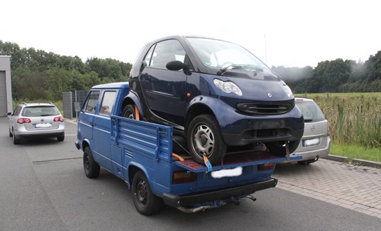
Figure 3 [Jan Bode]
Now it gets interesting.
In Figure 4, we see that there is a tire under the car. This is probably there to reduce the load on the front axle of the car that is being transported to prevent it from pushing down on the tailgate:
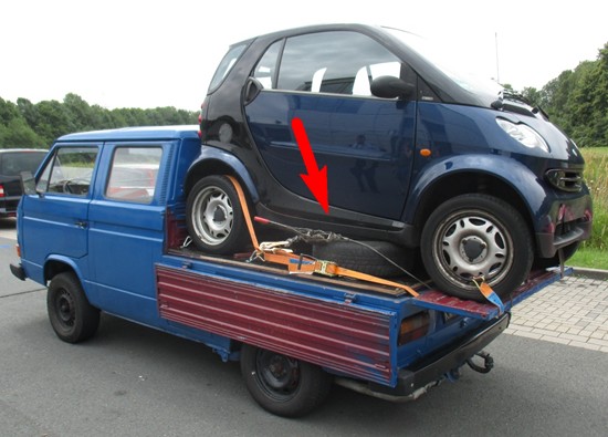
Figure 4 [Jan Bode]
So far so good. If we have a look at how the wire rope has been routed, it all gets a bit fraught. Believe it or not, the hook behind the ratchet has been hooked into the handle of the belt ratchet.
And that's not all. Let's have a look at the detail in Figure 4.1:
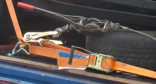
Figure 4.1 [Jan Bode]
The lashing belt from the front right wheel rim is hooked into a carabiner. Not just any old carabiner, but one that we might expect to use to suspend a hammock. With a maximum strength of 160 daN, this is not suitable for securing heavy loads.
Another lashing belt can be seen on the left of the photo. It has been hooked into the right-hand ratchet, runs through the carabiner we were just talking about, passes over the right rear tire and is then hooked into another "hammock carabiner" (see Figure 4).
The photos below show the right-hand side of the flatbed vehicle. Figure 5 shows the whole of the vehicle:
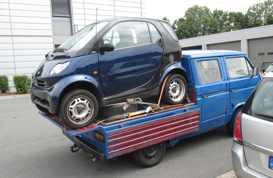
Figure 5 [Jan Bode]
Figure 5.1 again shows a detail to show the routing of the belts more clearly:
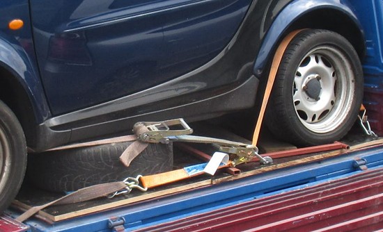
Figure 5.1 [Jan Bode]
On the right we again see two carabiner lashing points. The hook of a lashing belt has been attached to the left-hand carabiner. The belt passes forwards over the axle, under the tailgate and its claw hook ends up in a lashing hook. This lashing hook then forms the starting point for another lashing belt that runs through the carabiner, over the left rear tire of the Smart and ends up in the right-hand lashing point behind the tire.
You will need patience and probably a pair of spectacles to follow the convoluted paths taken by these lashings.
We do not know whether the manufacturer of the flatbed originally equipped it with lashing points. Either way, they are no longer present.
A textured coated board floor was subsequently fitted to the bed. This was then equipped with four lashing points of exquisite workmanship.
The photos below show them in more detail.
The lashing points are made up of a washer that has been drilled through and secured to the bed with a coach bolt. The washers were then bent upwards, and equipped with carabiners to accommodate the lashing hooks.
Figure 6 then shows a lashing belt that has been passed through the carabiner and squeezed through the lashing hook of another belt:
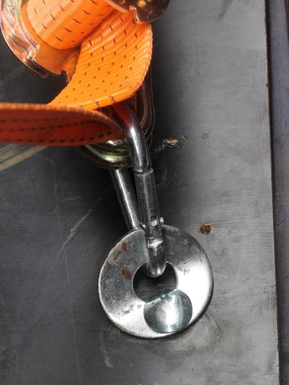
Figure 6 [Jan Bode]
Figure 7 shows another lashing point of the same construction:
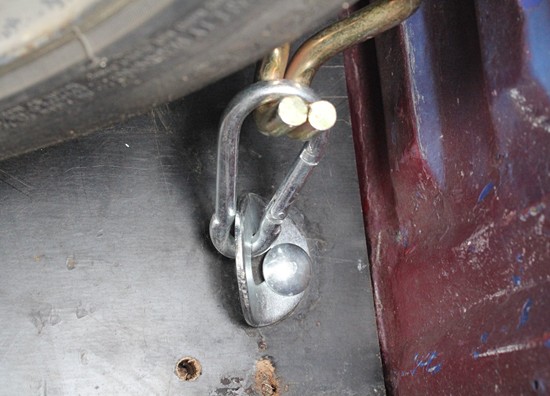
Figure 7 [Jan Bode]
Our first impression has been confirmed: The load has been secured dreadfully, and the lashing points provided are pathetic.
We have not described in detail the frightful state of the bottom of the vehicle. Everywhere you looked, there were places that had rusted through, indicating that an annual inspection would have led to the vehicle being taken off the road.
It is no surprise that the police stopped this vehicle. A driver who saw the vehicle being stopped gave the thumbs-up to the police officers.
So how can matters be rectified?
They can't! The police did not allow the vehicle to continue on its way. The driver and owner were issued with summonses for traffic offenses. The load had to be collected by a suitable transporter.
Information on the design of lashing points and how strong they have to be on vehicles with a maximum gross weight up to 3.5 t can be found in DIN 75410-1. According to this standard, the lashing points have to have a load capacity of at least 400 daN.
If cargo is to be transported, a suitable vehicle must be used. This must be in a roadworthy condition and capable of accommodating a load safely.
This also means that the permitted gross weight and the permitted axle loads must not be exceeded.
We wish you a safe and secure journey.
Your Load Securing Team
Back to beginning