
| Photo of the month – October 2014 |
[German version] |
Coil crash
In this column, we often warn that inadequate securing of loads can lead to a disaster. And this month, we again demonstrate the catastrophic consequences of a poorly secured load. And, to put your minds at rest, the driver survived. And in that sense, this disaster was not as bad as it might have been.
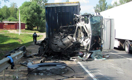
Figure 1 [Capt. Anatoly Shmelev]
This collision was caused by coils (slit strip coils) with a weight of 10 tonnes. These slit strip coils were not transported in a coil well, but were instead bundled together on a skid.
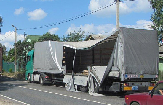
Figure 2 [Capt. Anatoly Shmelev]
This vehicle passed over a bump in the road at a bridge where the road curved slightly to the right. The driver reported that the vehicle „bounced“ over the bump. Unfortunately, we do not know whether he instinctively braked at the same time. The slit strip coils fell from the vehicle to the right and collided with the oncoming truck. For any oncoming cars, these 10-tonne coils would undoubtedly have caused a fatal accident. It is noteworthy that the vehicle was carrying 2 skids, each with 3 slit strip coils, i.e. a total load of 20 tonnes. The first skid, which was loaded on the front third of the vehicle, appears to have remained in place, even though it is reported to have been secured in exactly the same way as the second skid with the 3 slit strip coils.
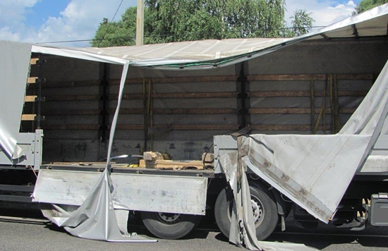
Figure 3 [Capt. Anatoly Shmelev]
Figure 3 shows the skid on which the 3 slit strip coils were loaded. We can see significant damage, particularly at the front of the skid, indicating that the coils rolled over the skid, along with loose steel straps which have clearly snapped. The slit strip coils then penetrated the side wall and the tarpaulin and fell onto the road.
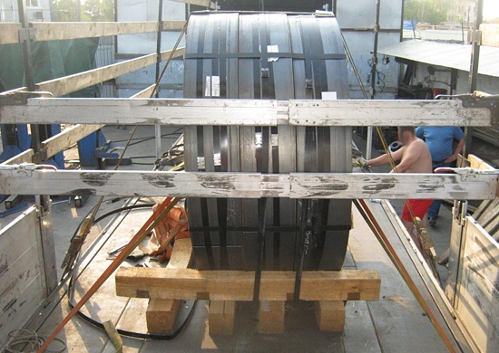
Figure 4 [Capt. Anatoly Shmelev]
According to reports, this shows how the coils were secured. A total of 6 belts and 2 retaining boards were used. Because loose steel strapping can be seen „scattered“ on this vehicle, we can assume that it is the vehicle involved in the accident. 2 retaining boards were indeed used, both in front of and behind the slit strip coils.
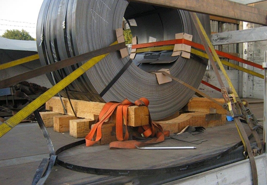
Figure 5 [Capt. Anatoly Shmelev]
Figure 5 shows the 3 slit strip coils from the side and gives a further insight into how the skid was built. The skid is built in such a way that the coil is not suspended in it, as it would be in a coil well, but rather stands on the skid, as is indicated by the fact that the bottom members are recessed to accommodate the coils. The lateral members are chamfered to better accommodate the coils.
Functions of the skid
The skids take the weight of the load and distribute it over the loading surface. The wooden members appear to us to be rather short. Given that the coils have a diameter of 1.60 m, the wooden members can be no longer than 2 m. We shall leave aside the question of whether the vehicle was capable of handling line loads of 5 t/m. On the right-hand side of the vehicle, we can see that the first longitudinal member of the skid is bearing none of the weight of the slit strip coils. This clearly indicates that the skids were not custom built for this load.
Bundling of the load
The slit strip coils were bundled using 32 mm steel strapping. They were held together by 2 steel straps around their circumference. In addition, we can see 2 steel straps acting as a kind of tie-down lashing to secure the slit strip coils to the skid. The slit strip coils are bundled to form a unit using at least 3 steel straps. This can be seen better on other pictures. We shall discuss this further when we look at a different picture.
Friction
Even though regular readers will be asking why we want to talk about friction in this particular case, we would nevertheless like to present as complete a picture as possible when talking about an incident of this magnitude. Figure 5 shows a large number of anti-slip mats, whose state indicates that they are ready for scrapping. The driver is on record as saying that he used anti-slip mats. But if we look at the load on Figure 5, we can see no rubber mats beneath the wooden members of the skid. If rubber is to be used in this situation, it must be placed under the load in such a way that it protrudes beyond the members of the skid on all sides. This absolutely guarantees that the members of the skid are completely isolated from the loading surface in terms of friction. With a heavy load such as this, the best way of doing this is to place anti-slip material across the entire area under the wooden members. So why is the use of friction-enhancing materials only of limited importance in this scenario?
The way that the cargo is loaded on this vehicle means that the primary risk if the vehicle has to break in an emergency is that the load will roll, and possibly roll over the skid.
Securing method
Before we have a look at the securing method, we want to comment on the quality of the belt material. In Figure 5 alone, we can see 4 places that indicate that the belts are ready for scrapping. We have highlighted these places in Figure 5a.:
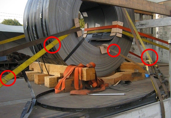
Figure 5a [Capt. Anatoly Shmelev]
Unfortunately, damage of this kind is commonplace with the belt material found on vehicles regularly used for transporting steel. Here it indicates that edge protection is clearly not regarded as particularly important, as evidenced by this picture. The edge protection comprises cardboard, which is already badly torn, particularly in the eye of the coil. Of course, this is due to the shape of the eye of the coil, but nevertheless clearly shows that too little thought was given to protecting the load-securing equipment, i.e. the belts. According to the information available to us, the cardboard edge protectors belonged to the carrier. The factory at which these slit strip coils were loaded clearly had no time for load-securing considerations.
The figure shows a total of 3 different securing methods.
- Direct lashing against movement to the front and rear
- A single tie-down lashing through the eye of the coil
- 3. 2 tie-down lashings that serve both to bundle the coils at the top and to lash them down. In other words, these belts were passed over the top of the coils, through the eye, over the coils again and tightened on the other side. It is highly unlikely that any tie-down lashing effect, particularly on the opposite side, will have been achieved with so many changes of direction, although there would have been a certain bundling effect at the top of the coils. There is no sign that the slit strip coils had been secured to the side other than by the friction that was present and the tie-down lashings intended to increase this friction.
In addition to the tie-down lashings, 2 retaining boards were used to prevent the coils from rolling forwards. This picture only shows one of these (Figure 4 shows both the boards).
We shall assess the effect of the load-securing measures taken and present the measures that would actually have been necessary in detail below.
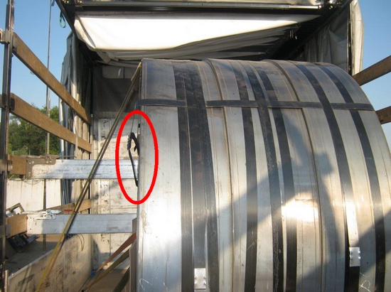
Figure 6 [Capt. Anatoly Shmelev]
Figure 6 shows the 2 steel straps around each of the slit strip coils to prevent the 4-mm thick hot-rolled steel strip from uncoiling. We can also see the 2 steel straps used to secure the slit strip coils to the skid and 1 of 3 or possibly 4 steel straps used to bundle the coils to form a load unit. Because the slit strip coils fell from the vehicle to the right-hand side, we have to ask how effective the attempt was to bundle the slit strip coils to form a single full-sized coil. At the point indicated by the red circle in the picture, it can clearly be seen that at least 1 of the straps used to bundle the load is relatively loose. This is hardly surprising, because the slit strip coils would probably have been loaded on the truck together with the skid, and the loading operation would undoubtedly have caused lateral loads to act on the upright coils, causing them to tilt to the side. This movement would have been sufficient to elongate the steel straps.
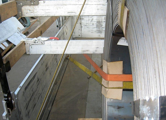
Figure 7 [Capt. Anatoly Shmelev]
Figure 7 shows that the tie-down lashing is not purely a tie-down lashing, but that the belts have been passed over the coils, back through the eye and lashed down on the opposite side. The driver used 2 belts to do this in order to bundle the slit strip coils together better. This is compelling evidence that the driver was fully aware of the inadequate packaging and bundling of the slit strip coils. Figure 7 also shows that the edge protectors are made from relatively heavy cardboard, but, as we saw in Figure 5, this was pushed to its limits in the eye of the coil. It probably only makes sense to use edge protectors like this with packages of steel sheets or steel boxes that have straight edges so that the edge protector material does not have to be pressed into a curve.
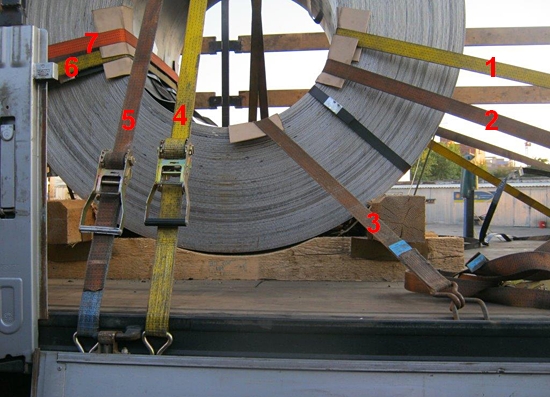
Figure 8 [Capt. Anatoly Shmelev]
Assessment of the load-securing measures
Whenever a load is secured, steps must be taken to ensure that it is secured against an acceleration of 0.8 g longitudinally and 0.5 g laterally. In the case of this load, we have to ask whether the usually good coefficient of friction µ of 0.3 (some people even use a value of 0.4) for rough-sawn lumber on textured coated board should be used. Because we already know the results of the load-securing measures taken here, the answer has to be no. So what, in all probability, happened?
When the truck passed over a bump or the joint between the bridge and the road, at the same time negotiating a slight bend to the right, the slit strip coils probably tipped to the left, and in doing so (probably) tore the bundling belts 4 and 5. They then rolled over the skid, (probably) causing the direct lashings 1 and 2 to fail. After the coils had fallen on their sides and/or rolled, they then cut through the edge protectors of the tie-down lashing 3 and the direct lashings 6 and 7 and fell onto the road. There they collided with the oncoming traffic at an aggregate speed of 120 kph (60 + 60).
Securing in the direction of travel
Because it must be assumed that the load has a tendency to roll over the skid, and taking into consideration that the load unit appears to be far from stable, it must also be assumed that the load must be secured against rolling. In other words, friction cannot be taken into consideration. This being the case, the use of 2 belts as direct lashings would be inadequate to secure the load against rolling, no matter how well they were placed. It would have been necessary to use at least 3 belts in this case. Furthermore, each of the pairs of direct lashings were secured to the corresponding load securing points on the opposite side of the vehicle. This is a cardinal error with direct lashings, because the load must move forwards slightly in order to allow the belts to bring their entire lashing capacity (LC) to bear when direct lashings are used. But in this case, if the coil moves forwards a few centimeters, the different length belts will be tensioned to different degrees. First, the short belt will be subjected to a load up to its LC, and will then fail, followed by the longer belt, which will then also be subjected to a load up to its LC and then fail. This means that, in this case, 3 belts would have been necessary. The lashing points to which these belts were attached should have been offset in order for the belts to be all of the same length, as shown in Diagram 9.
The load must be secured to the rear against an acceleration of 0.5 g. Here also there is the risk that the slit strip coils will roll over the skid. Which means that the entire weight of the load must be secured. 0.5 x 10 results in 5 t, and 2 intact belts could be used to adequately secure the slit strip coils to the rear, provided that these belts also are placed in such a way that they have equal working lengths. Again, this was not the case here. We have already mentioned the quality of the belts in general above.
Securing to the sides
In this case, the load was secured to the sides with the round-turn lashings 5 and 4. This is entirely insufficient to secure the load to the side. This measure was probably taken because of the inadequate or loose bundling of the slit strip coils. But virtually no securing effect to the sides could be achieved in this way because the slit strip coils were able to move back and forth in the round-turn lashings. When a load like this needs to be secured to the sides, it can be done as follows:
The belts must be placed as loop lashings alternately from both the right and left sides, passing round the top part of the coil towards 12 o’clock. The bottom of the coil must also be prevented from slipping sideways with a total of 4 loop lashings. Because the bundling was clearly wholly inadequate, the coil is not firmly secured to the skid. This being the case, the use of anti-slip materials under the skid to increase friction in order to secure the load to the sides would also not have provided a sufficient securing effect. What is needed is 4 loop lashings, 2 at the back and 2 at the front at the bottom of the coil, in order to keep it firmly in position. This means that the following direct lashings would be used to secure the load to the sides: 2 at the top of the coil, at 12 o’clock, and 4 at the bottom, 2 at 4 o’clock and 2 at 8 o’clock. It goes without saying that undamaged belts must be used with appropriate edge protectors, preferably made from rigid edge protector components specially designed for use with steel loads.
Notes on execution
In order to prevent the loop lashings attached at the top of the coil to secure it to the sides from slipping off the coil when the vehicle brakes, for instance, plenty of anti-slip material must be placed under these direct lashings on both sides.
The driver was right to doubt that the slit strip coils had been bundled adequately. If they are secured with direct lashings both at the base and at the top, they would be pushed together by the pre-tensioning force of the belts and this would compensate for the inadequate bundling. To further compensate for the inadequate packaging at the top of the coils, we would recommend additional bundling belts around the slit strip coils at 10 o’clock and 2 o’clock.
Tie-down lashings
Tie-down lashing 3 indeed acts almost purely as a tie-down lashing. Given a load that has a tendency to roll, extremely low friction and a load weight of 10 tonnes, the driver would hardly have intended this lashing to secure the load by increasing friction. Instead, he may well have intended it as a direct lashing in an upward direction, which would have achieved a welcome reduction in vertical movement on poor roads such as this inadequate bridge approach.
How can this cargo be loaded securely and correctly? If we consider the securing method we have proposed, we come to a total of 13 belts, some of which are used for bundling the load, and the rest of which are direct lashings to hold the coil in position. To secure this load, where a total of 6 slit strip coils (2 x 3) were transported on 2 skids, a total of 26 belts are needed, along with considerably more edge protection material, and the work needs to be carried out diligently, properly, and with a great deal of thought. In our opinion, cargo of this type should be transported on a vehicle with a coil well, where a tight fit can be achieved against robust stanchions, which in turn should preferably be braced diagonally to the front. Suitable load-securing points capable of withstanding 5,000 and 10,000 daN (and appropriate chains and belts) should also be available for use.
Retaining boards:
The use of retaining boards for securing loads is a common sight. Some of these engage with a side wall as a tight fit, but these are not proper retaining boards. The retaining boards used here were secured to the removable wooden slats and provide a securing force that undoubtedly lies somewhere between 30 and 80 daN, assuming that only new material is used. With a required securing force of 8000 daN, the use of retaining boards is more an act of desperation than an effective securing method. Retaining boards can be used, for instance, to secure light boxes that are liable to tip, where they provide a useful securing mechanism.
Securing a coil in the direction in which it is liable to roll is undoubtedly a serious challenge.
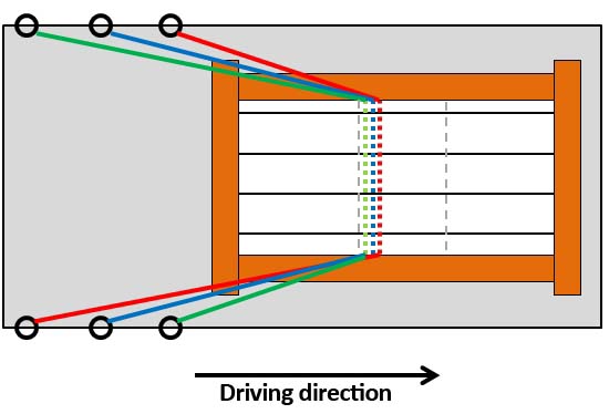
Figure 9 [GDV]
Arranging the belts in this way ensures that they all have the same length. It is important that the edge protectors allow the belts to slip over them. If the slit strip coils accelerate forwards during emergency braking, the belts must stretch to reach their LC. The asymmetrically arranged belts must slip through the eye of the slit strip coils slightly on their edge protectors. Consequently, it is important that the edge protector has guides to the sides and has a low coefficient of friction on the side in contact with the belt, and the belts must under no circumstances be placed on top of each other.
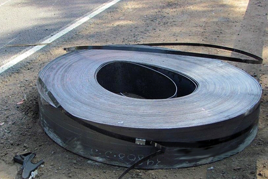
Figure 10 [Capt. Anatoly Shmelev]
Responsibility
To start with, we can say that it was fortunate that the driver survived the accident and we very much hope that his injuries were not too serious. It is clear to everybody that there would have been several fatalities if the oncoming traffic had been cars. So who is responsible?
As always, it is the driver, but also the loader and the carrier. In Germany at least, the courts would investigate the issue of whether the cargo was loaded in such a manner as to be safe for transport. And, in Germany, the loader is responsible for this aspect. As a general point, loaders across the world must ask themselves how it is possible for a driver to be confronted with a task of this magnitude without any assistance. And how it is possible for a steel factory or a steel dealer to allow a driver to secure such a dangerous load incorrectly and inadequately using some belts that are clearly fit for scrapping and obviously make no attempt to inspect the way in which the load has been secured. We hope that this accident will serve as a warning to all loaders to take all of their responsibilities seriously. Drivers must not be allowed to face such challenges alone. The carrier must face up to the question of why they did not use a vehicle with a coil well for this cargo. If no such vehicle is available, the driver must have received excellent training in load securing and the vehicle must be extremely well equipped with load-securing materials. Belts that are fit for scrapping must be scrapped.
We wish you a safe and secure journey. Your Load Securing Team
Back to beginning