| Photo of the month – February 2013 |
[German version] |
|
The dull days of winter provide an ideal opportunity for reflecting on the curiosities of life on land and sea. And so, we have two photos of the month for you this month. |
|

|

|
| Potemkin end wall | Diving lessons – or the necessity of navigation |
|
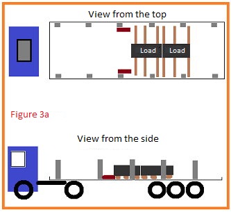
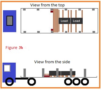
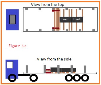
Potemkin end wall Perhaps the reference to Potemkin villages may be somewhat literary, but it is nevertheless apt in this case. Prince Grigory Aleksandrovich Potemkin may well have erected sham villages to impress the Empress, and this end wall is no less of a deception, albeit a self-deception. In reality, this is not an end wall, but rather something that is pretending to be one. But let’s start at the beginning. 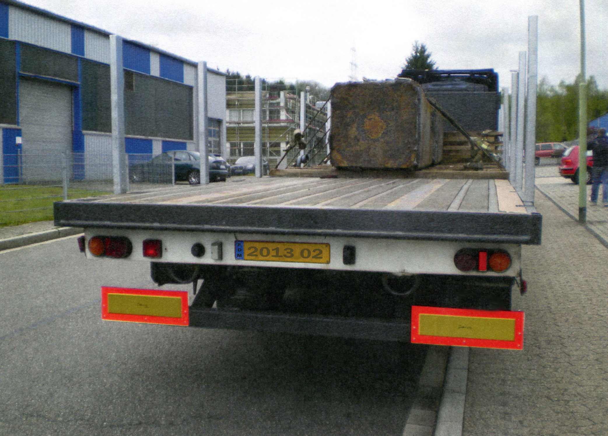 Figure 1 [Peter Scholz] This vehicle is a flatbed semitrailer with 6 stanchions on each side. The load consists of two cast steel blocks weighing 8 t and 6 t. 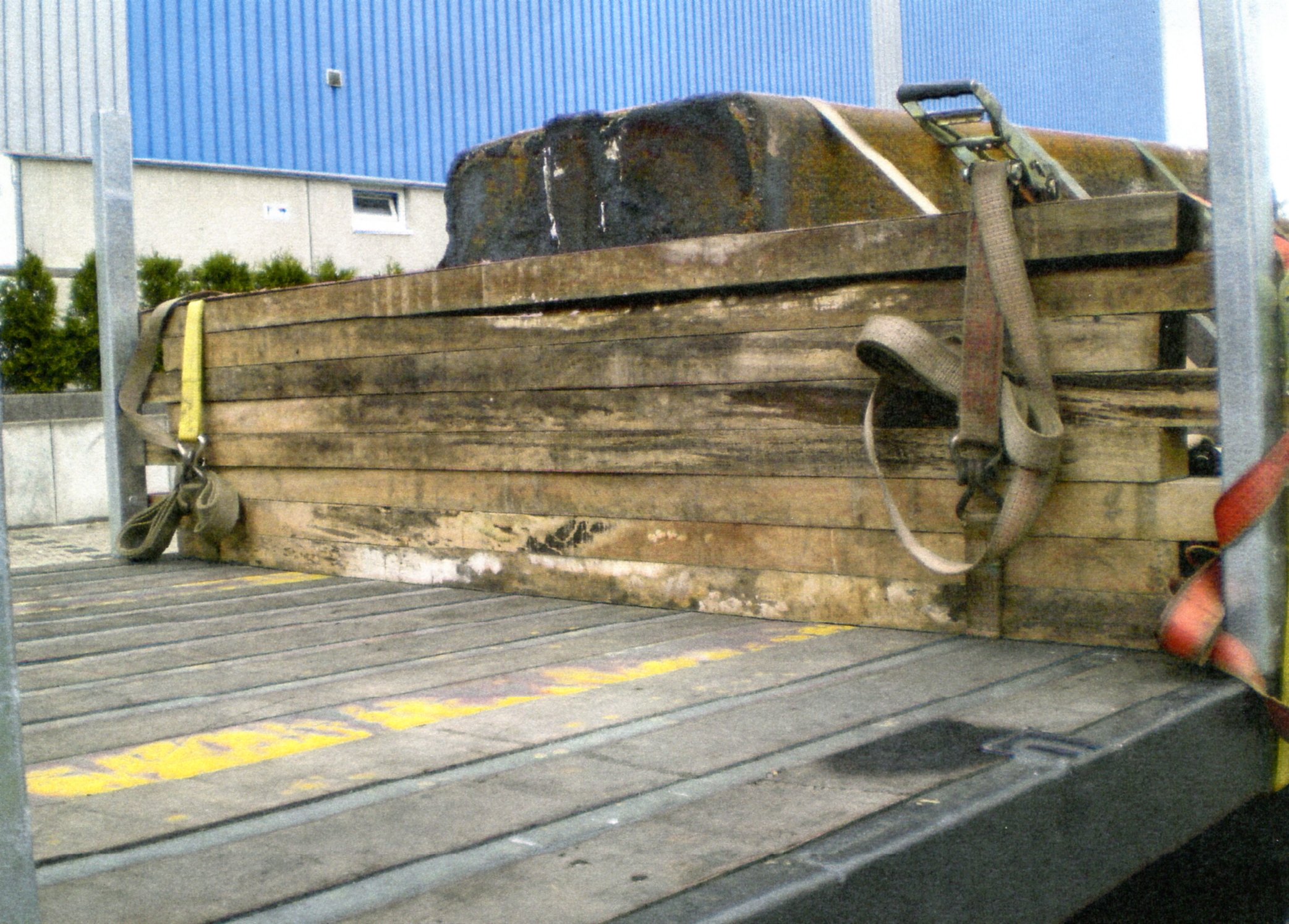 Figure 2 [Peter Scholz] The considerable weight of these cast steel components clearly motivated the driver to secure this load particularly well. And because tight-fit securing is generally regarded as an excellent method (which it is), he attempted to construct an artificial end wall. To achieve this, he stacked 8 lengths of squared lumber and bundled them together with belts. But because the lengths of lumber were around 20 cm too short to rest tightly against both stanchions at the same time, each alternate length of lumber was placed against one stanchion and secured with belts. In principle, tight-fit securing is one of the best methods of securing a load available to us, particularly when it is able to withstand high loads. Let us for the moment ignore the method behind the attempt to achieve a tight fit in this example. The first thing you always have to ask is how strong are the components against which you intend to place the load. Depending on the thickness of the material used for the stanchions, we can safely assume that each stanchion has a load capacity of 3000 daN. The higher the load is applied, the lower the securing force the stanchions are able to exert against the load. Of course, stanchions like this can be constructed in such a way that they are able to provide considerably more securing force. But if we take a look at this alternating end wall construction, it begs the question as to what happens at the ends that are not tight against the stanchions. And not without reason: If this Potemkin edifice was subjected to a load, it would open up like a fan towards the front. The only brief resistance that can be expected is provided by the belts. Because they have been used to bundle the lumber vertically, however, they only work in the same way as a tie-down lashing, and their effect can be ignored. Even though this end wall offers an impressive appearance, the reality is that its load securing capacity is negligible. 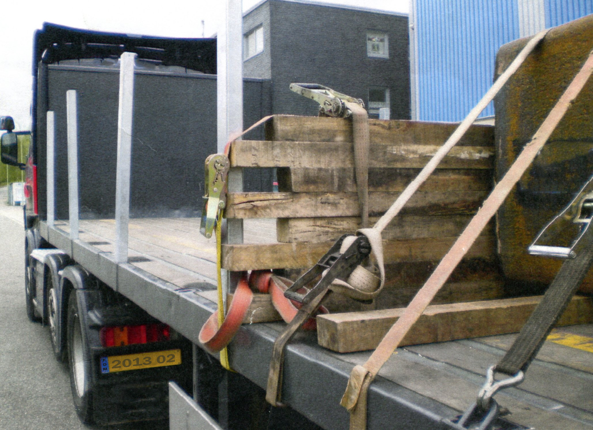 Figure 3 [Peter Scholz] Let us have a closer look at the idea behind this end wall. As we have already said, an end wall or an artificial end wall is a thoroughly sensible approach. If we ignore the alternating tight-fit at this end wall, we notice the following: The bottom length of squared lumber serves only to raise the lengths of squared lumber on top of it to a height that allows them to come into contact with the load, which has also been placed on squared lumber. If you wished to save material at this point, it would be perfectly sufficient to place short lengths of lumber lengthwise against the inner edge of the stanchions. Secondly, we notice that the driver has built the end wall as high as possible. Because in this case the load units are quite clearly compact, it would be perfectly possible to prevent them from slipping by placing just the bottom of the load as a tight fit against the stanchions. The following approach for connecting the load to the stanchions would make sense:
This 48 cm platform is now far stronger than 4 stacked lengths of lumber and any force is applied to the two stanchions at a relatively low point. At this point, the stanchions will probably provide a securing force significantly higher than a "mere" 3000 daN. If we assume a securing force of 6000 daN from the stanchions and a coefficient of friction µ of 0.3, we can calculate as follows for a weight force of 14,000 daN for the load: A total of 11,200 daN securing force to the front is required. We assume a coefficient of friction of 0.3 because no friction-enhancing materials (other than wood) have been used. This means that friction provides a securing force of 4200 daN. The remaining securing force is 7000 daN. If, for the sake of argument, we assume that the lumbar barrier we have constructed is "only" able to provide 6000 daN of securing force, the tie-down lashings have to deliver the rest. In this example, 10 tie-down lashings with long-lever ratchet tensioners have been used. Indeed, these were even pre-tensioned on alternating sides. We assume that the total pre-tensioning force for each tie-down lashing is 750 daN, giving a total of 7500 daN of pre-tensioning force. When we multiply this by 0.3, 2250 daN remain, which easily makes up the deficit in securing force. If we have a look at the belts on Figure 3 or on Figure 4 a little more closely, we can see significant signs of wear and tear that allow us to assume that most of the belts are probably fit for scrapping. 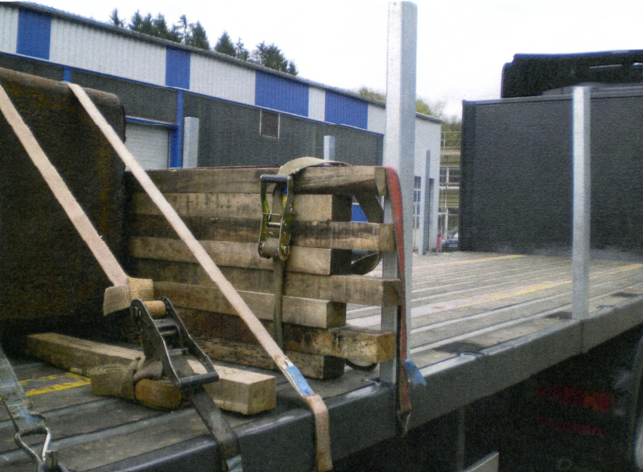 Figure 4 [Peter Scholz] At the bottom right of Figure 4, we can also see signs of wear and tear on the belts that indicate that they are at the very least near to the end of their life, or possibly that they should have been scrapped long ago. At this point, it is again worth pointing out that it is a waste of time and effort for drivers and/or loaders to attempt to "secure" a load using materials that should have been scrapped long ago. Because such extensive wear and tear, including tears in the belts, dramatically reduces their securing capacity, the time and effort expended only delivers 10 or maybe 20 percent of the expected results. 80 percent of the effort expended is in vain. What a waste of time! 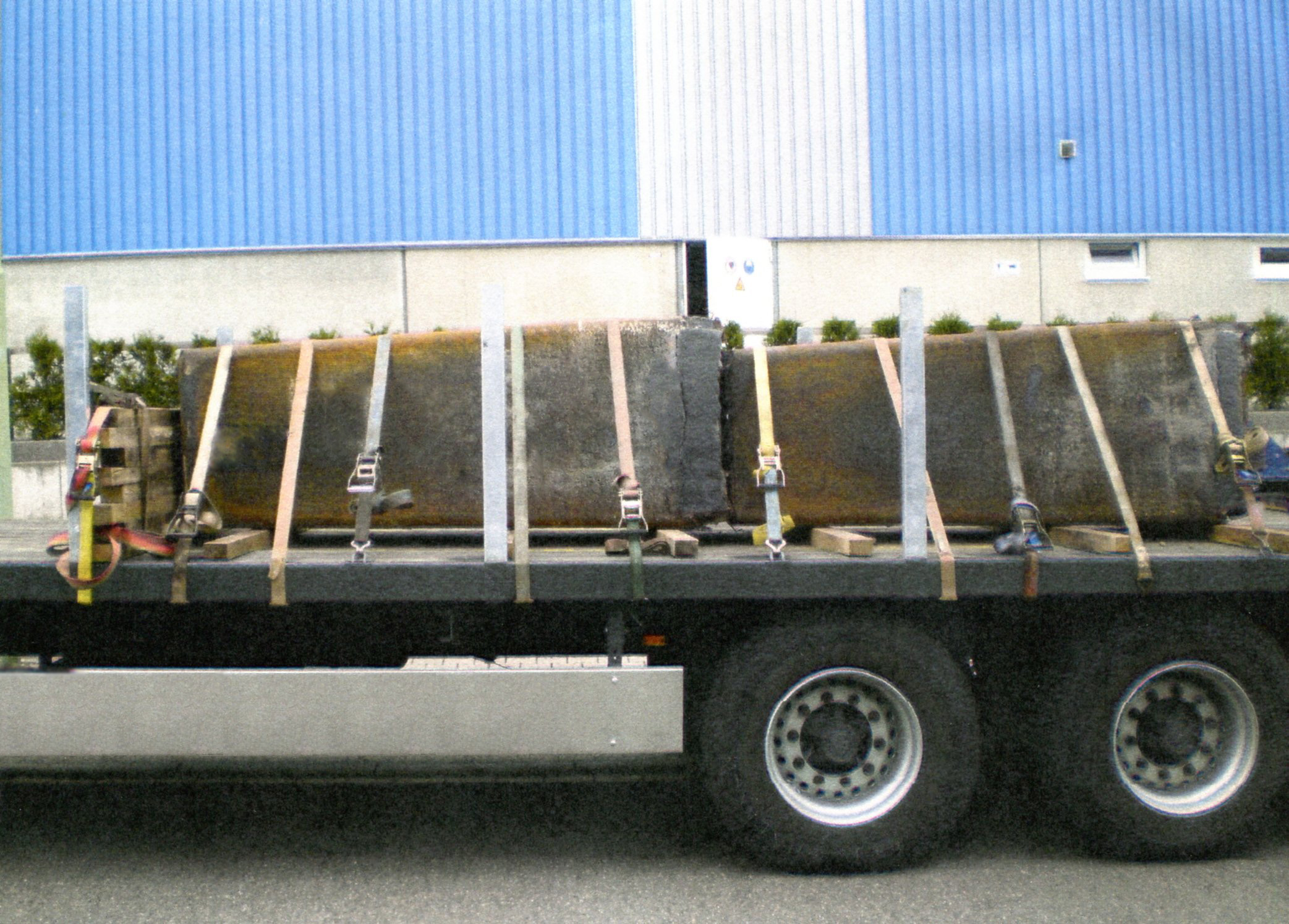 Figure 5 [Peter Scholz] This figure clearly shows the 10 belts placed in alternating directions across the load. Another positive aspect is that the dunnage placed below the load is approximately rectangular in cross-section (10 x 12 cm). A format such as this is far less liable to roll than a square cross-section. It is difficult to understand why friction-enhancing mats were not used here. Of course, they should have been used under the dunnage and under the load itself. The use of these rubber mats alone would have increased the load-securing effect of the belts from 2250 daN to 4500 daN. And if this had been done, it would have completely secured the load to the rear, an aspect which had been completely ignored. When you consider that the driver used 3 belts with long-lever ratchet tensioners to construct his "end wall", and undoubtedly needed to invest a considerable amount of time building his Potemkin wall, you have to ask why he didn’t use these belts as direct lashings around the end of the metal blocks. It would have been no problem to use a burden chain or a lifting sling to create a direct lashing here. But even if burden chains or lifting slings were not used, direct lashings placed crosswise would have provided a very good securing method. A single direct lashing on the level of the loading surface would have provided 4000 daN of securing force. These direct lashings could have been laid over lateral wooden beams to prevent them from slipping off and suitable edge protectors could have been used to protect the belts from the sharp edges of the cast metal components. If the belts were of sufficient length (10 or 12 m), the resulting angles would have been so acute as to be negligible. 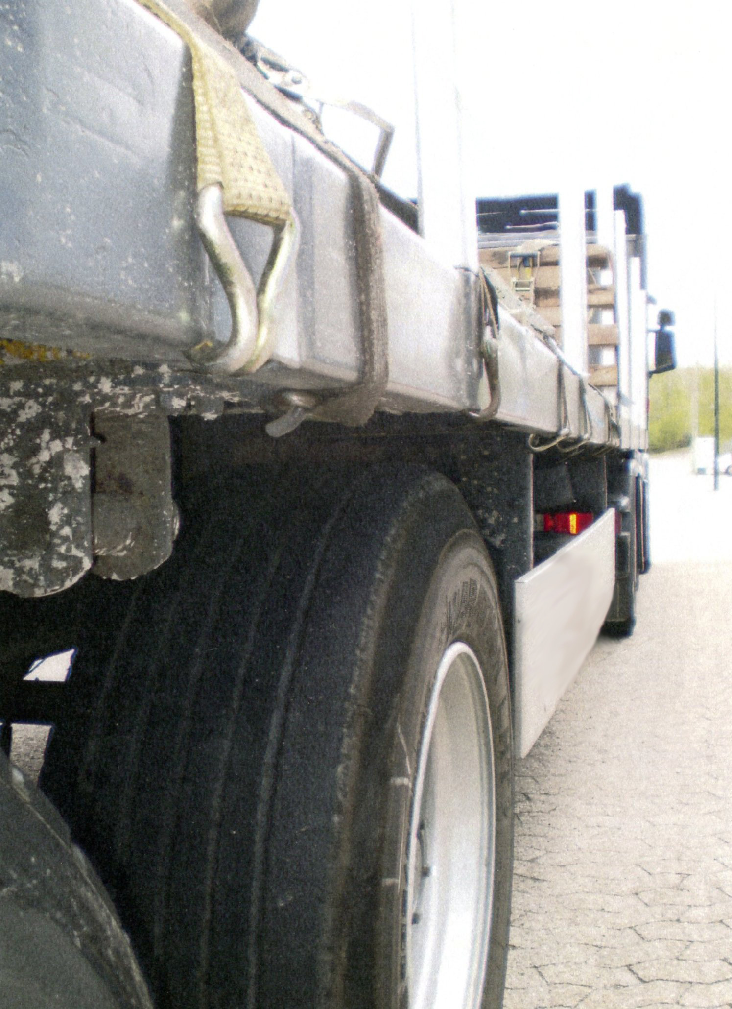 Figure 6 [Peter Scholz] This figure again illustrates the dilemma faced by loaders when a vehicle is equipped with belts, but there are insufficient load-securing points to accommodate them. All the hooks were belt hooks, which are ideal for inserting into load-securing points. But here, they were attached to the vehicle in any way they could be and very few of the hooks are loaded on the shoulder. Instead, they are loaded on the points, and most are liable to bend. It is no surprise that the belts and the hooks become damaged over time if they are treated in this way. To exacerbate matters, these belts and hooks will not be able to achieve their real securing capacity when needed, because they will be loaded incorrectly. 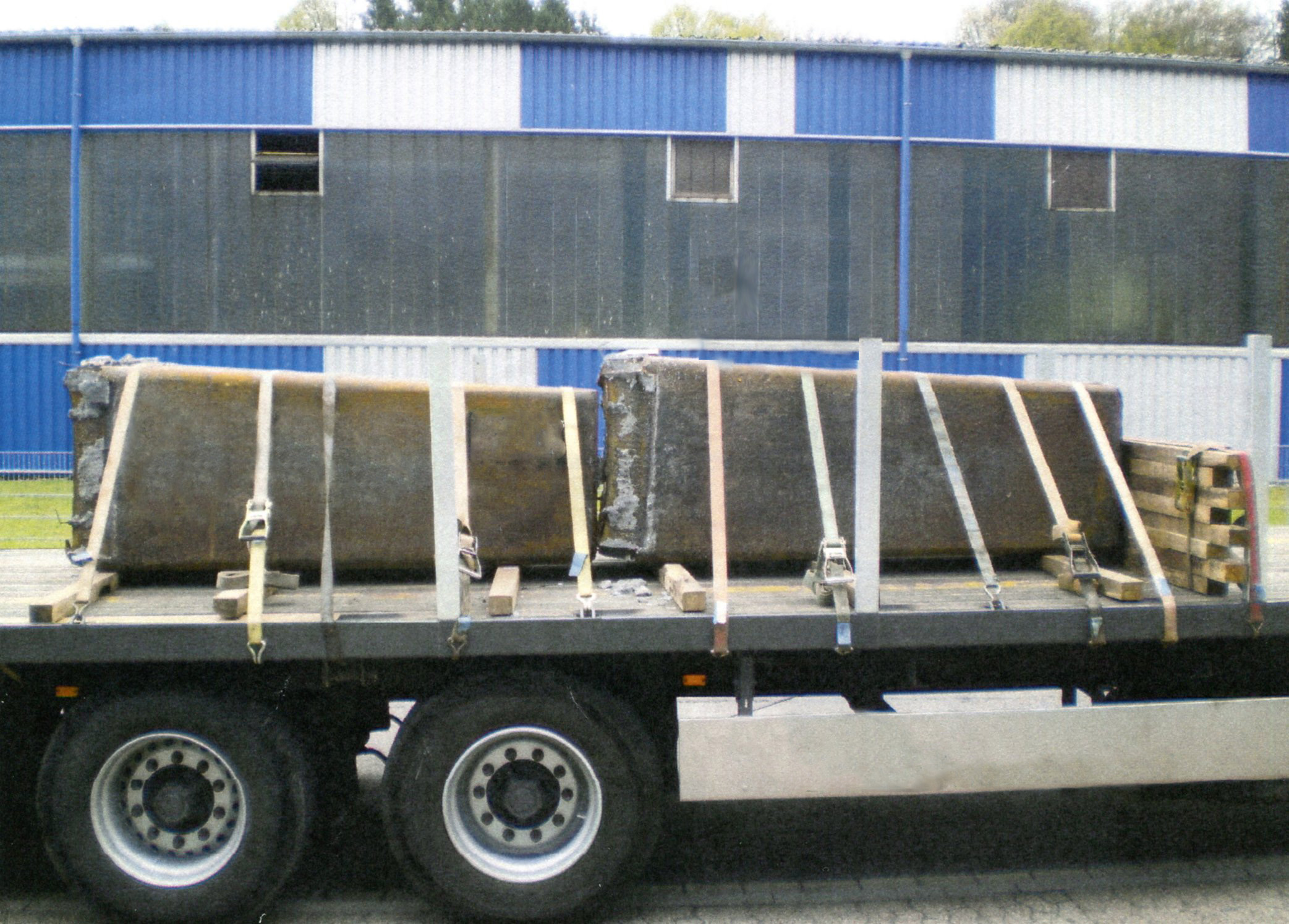 Figure 7 [Peter Scholz] As we come to a close, we should like to offer a little praise. This praise is due to the distribution of the load. In total, this vehicle was carrying a load of just 14 t. Nevertheless, the driver was careful to ensure that the load was positioned exactly according to the load distribution plan. According to add diagrams, we calculated that the overall center of gravity was located 40 – 50 cm in front of the first axle, which approximately corresponds to the maximum point in the load distribution curve. Closing comments: It would be ungenerous of us to dismiss this case as an example of good intentions and poor execution. Somebody thought long and hard about securing this load. The load distribution is good and the tie-down lashings have an angle of around 60° and use long-lever ratchet tensioners, which means that they are almost adequate for securing the load to the side. The dunnage under the load is only just rectangular, but at least it does not have a square cross-section, and the attempt to build an end wall was essentially good and praiseworthy, and only fell short by 20 – 30 cm. We shall not comment on the fact that parts of the load on the right of the vehicle appear to have dropped off and could fall onto the road. Back to beginning | ||||||||||