
| Photo of the month – May 2009 |
[German version] |
No oncoming traffic!
The articulated truck shown in Figure 1 was forced to perform an emergency braking maneuver because the driver saw a red light too late. The load included a 21-tonne cast block and the inertia of the load, coupled with the fact that it was clearly inadequately secured, resulted in the load moving relative to the loading area. It could be said that the vehicle outbraked the load.
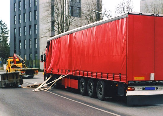
Figure 1 [Kreppold, PHM/A]
The cast block broke through the front left side of the vehicle. It can be seen on the left edge of Figure 1. Figure 2 shows that the vehicle was in a right-hand bend while it was braking. As a consequence the cast block accelerated towards the front and left relative to the direction of travel of the vehicle. The fundamental task of any load securing mechanism is to physically transmit information to the load as to the direction in which the vehicle is currently moving or accelerating.
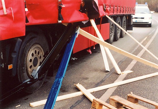
Figure 2 [Kreppold, PHM/A]
The skid mark of around 2 meters indicates that the braking maneuver must have been severe:
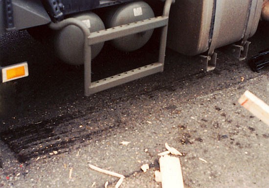
Figure 3 [Kreppold, PHM/A]
The body of the curtainsider is incapable of withstanding such forces. And this is simply not its task unless it features specially reinforced structures, for instance for securing crates of bottles etc. A view of the interior (see Figure 6) reveals that this is a standard curtainsider that has not been reinforced. The dimensions of the cast block show that there was a gap between the load and each side. The cumulative acceleration in particular (emergency braking and a change in direction to the right) accelerated the cast block not only to the side, but also forwards, with the result that the distance available for it to slide diagonally over the loading area was far longer. Even a trailer with fixed sides or a closed box body would not have been able to dissipate the kinetic energy generated by such a heavy load.
The point at which the load made contract with the road surface suggests the forces that must have been at work here:
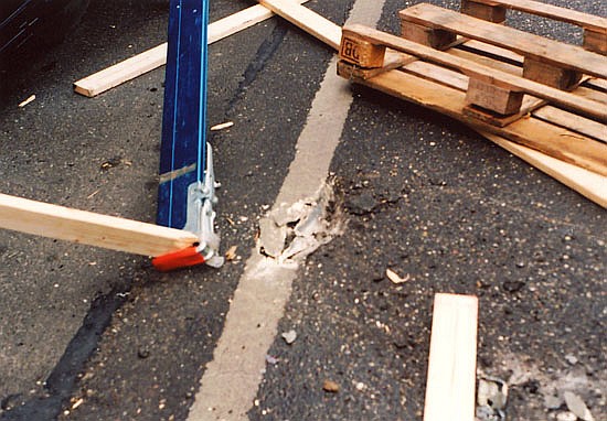
Figure 4 [Kreppold, PHM/A]
The 21-tonne cast block came to rest on the opposite side of the road, that was fortunately not carrying any traffic at the time of the accident. There is undoubtedly no need to discuss in any more detail the danger arising from the situation shown in this photo (Figure 5):
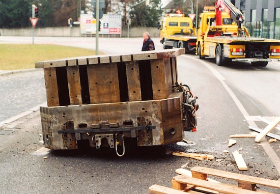
Figure 5 [Kreppold, PHM/A]
According to the police reports, the cast block was loaded in the front third of the trailer. Comparing this situation with common load distribution plans for trailers immediately reveals a gross error in load distribution. The load securing measures at least involved four belts attached diagonally, but unfortunately, these took the form of tie-down lashings strapped across the load.
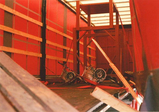
Figure 6 [Kreppold, PHM/A]
How could a load such as this have been secured correctly?
To start with, the load must be distributed correctly. A load with this sort of weight can only be loaded at exactly the point at which the load distribution curve of the trailer reaches its maximum. As a rule, this is just in front of the first axle of the 3-axle unit of the trailer. Then it is necessary to check whether the line load capacity of the trailer is sufficient to accommodate such a high load over such a short length. In other words, it is necessary to check whether the loading area is capable of withstanding 21 tonnes over a length of around 1 m or 1½ m. This will generally not be the case, and as a result, the load must be distributed over the loading area using wooden or even steel beams.
As is always the case with load securing, friction is a significant issue. Because acceleration on the loading area is directly related to the high level of friction between the tires and the road surface, it makes sense to ensure that a similarly high level of friction is provided between the load and the loading area. This can be achieved using friction-enhancing mats. In the case of a used cast component such as this, it can be expected that oil will still be dripping from the hydraulic connections that can still be seen. For this reason, it is important to select anti-slip mats of a type that are not sensitive to being coated with oil and that are nevertheless still capable of withstanding such high loads. If it is necessary to place lumber or steel sections under the load to distribute the load, the friction-enhancing material must be placed both on top of and beneath the load-distributing elements in order to transmit the friction forces to the load homogeneously. Such elements are referred to as sandwich elements, because FE mats are placed on the top and bottom like the bread in a sandwich.
Load securing measures:
We can now assume a theoretical coefficient of friction μ of 0.6. This means that 0.2 g still need to be secured in a longitudinal direction. With a load of a weight of 21,000 kg, this corresponds to approx. 4,200 daN. Our proposal for securing this load would be to use two loop lashings to secure the cast block to the front and one loop lashing to each side and to the rear. If the load securing equipment comes into contact with sharp edges, appropriate protective measures must be taken (protective sleeves, corner protectors, etc.). The two loop lashings to the front must be attached to different load securing points. If you were to attach the first loop lashing to the two load securing points located directly behind the cast component on the vehicle chassis, and then to attach the next loop lashing to the next two points further back, this would result in one short loop lashing and one long one. This is not ideal when a load is applied, because the shorter belt would stretch less and thus be loaded considerably before the longer belt. We therefore recommend that the load securing belts should be attached asymmetrically, i.e. by using the front load securing point on one side and the rear point on the other side. Any asymmetrical forces that would arise from this on loading are canceled out by the use of two loop lashings. The diagram below illustrates this asymmetry. The two loop lashings are shown in red and blue to distinguish them.
For the sake of clarity, the loop lashings to the sides and to the rear are not shown.
Review:
In theory, everything is now perfectly okay. A securing force of some 8,000 daN is now acting to the front and 4,000 daN is acting to the sides and to the rear. Given a coefficient of friction of 0.6 and maximum acceleration to the side of 0.5, the loop lashings to the sides and to the rear meet the minimum load securing requirements. However, because the cast block is coated with oil and it is possible that further oil may be lost during transportation, we recommend that the theoretical coefficient of friction of the FE mats is reduced to 0.4 and that the securing measures should then be reviewed in this light. This is an additional safety measure that you will not find in any directives, but which is not too much to ask of a responsible road user. If you review the situation under these conditions, it is revealed that there is a shortfall in securing force of a good 400 daN to the front. This can be achieved with an additional third loop lashing.
To allow three belts of equal length to be used for the three loop lashings, we recommend that two belts are attached asymmetrically and the third belt symmetrically. Three load securing points must be used on each side to achieve this. Attach the first two belts asymmetrically from the front load securing point on one side to the rear load securing point on the other side. These two lashings are shown in red and blue in the diagram below. The third lashing is attached symmetrically and uses the middle load securing point on each side. This lashing is shown in yellow in the drawing:
For the sake of clarity, the loop lashings to the sides and to the rear are not shown.
As an alternative to this additional loop lashing, the additional 400 daN securing force required can be provided by two tie-down lashings.
And if anyone is asking why it is necessary to be so excessively careful, we would recommend that they have another careful look at Figure 5. We believe that this figure clearly reveals the considerable potential hazard. Anyone who looks at the picture and still thinks that the proposed load securing measures are excessive should imagine an oncoming vehicle that is passing the scene just at the moment of the accident.
Back to beginning